Sealing-equipped oil pan

Active Publication Date: 2016-08-04
AISIN AW CO LTD
View PDF1 Cites 6 Cited by
  • Summary
  • Abstract
  • Description
  • Claims
  • Application Information

AI Technical Summary

Benefits of technology

[0011]With this configuration, since the projection of the sealing member is supported by the base portion of the oil pan, a tilt of the sealing member with respect to the r

Problems solved by technology

However, in such a general assembly, when the oil pan is attached to the target device with the gasket placed on the oil pan, if the rim portion of the oil pan has a long straight portion, the gasket tends to tilt

Method used


Image

  • Sealing-equipped oil pan
  • Sealing-equipped oil pan
  • Sealing-equipped oil pan

Examples


Example

[0020]An embodiment will be described with reference to FIGS. 1 to 6. In the following description, a sealing-equipped oil pan 1 according to the embodiment is attached to an automatic transmission (a target device) mounted in a vehicle, for example. However, the sealing-equipped oil pan 1 is not necessarily attached to the automatic transmission and can be attached to any device in which oil is circulated, such as a hybrid driving device or an engine.

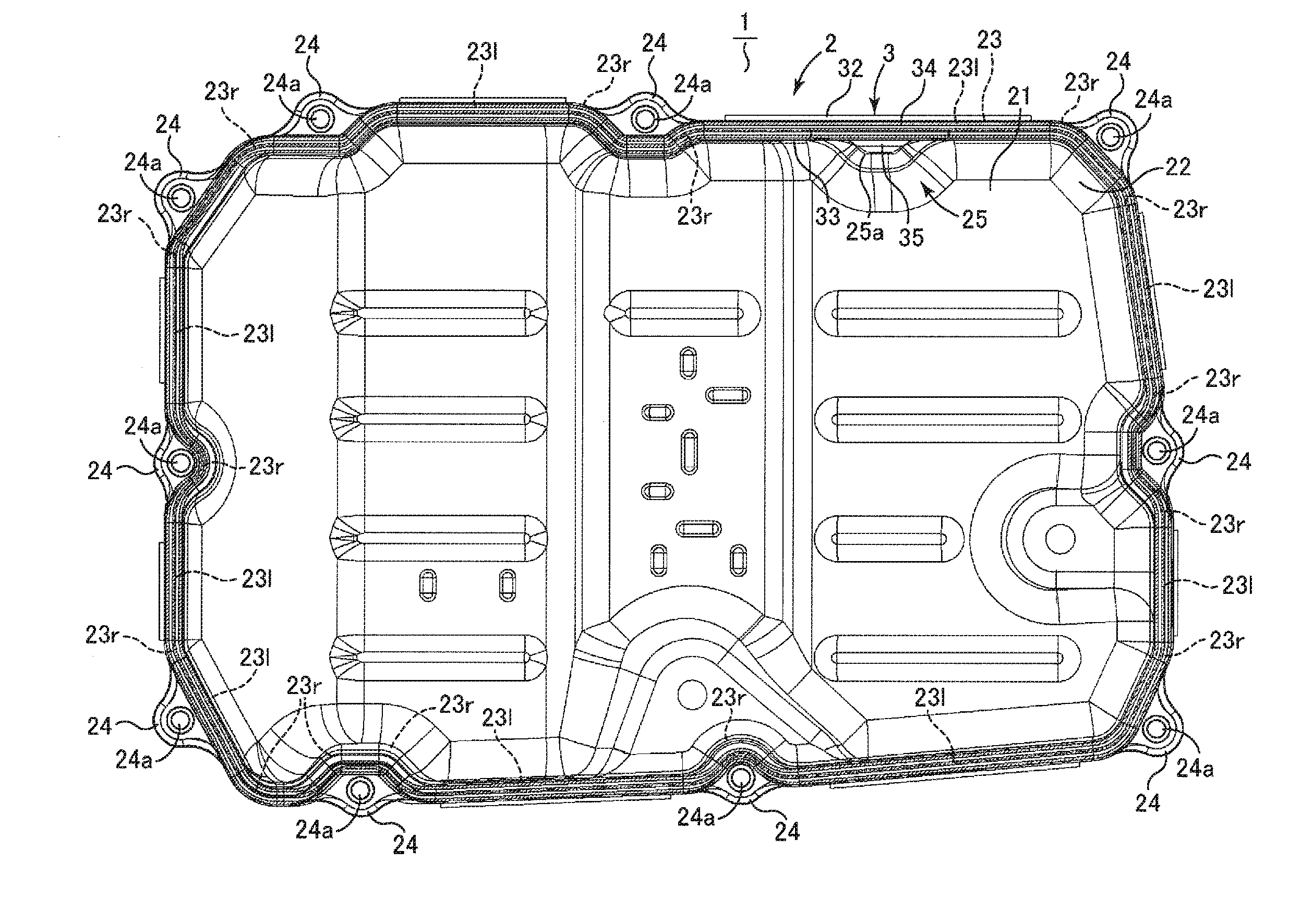
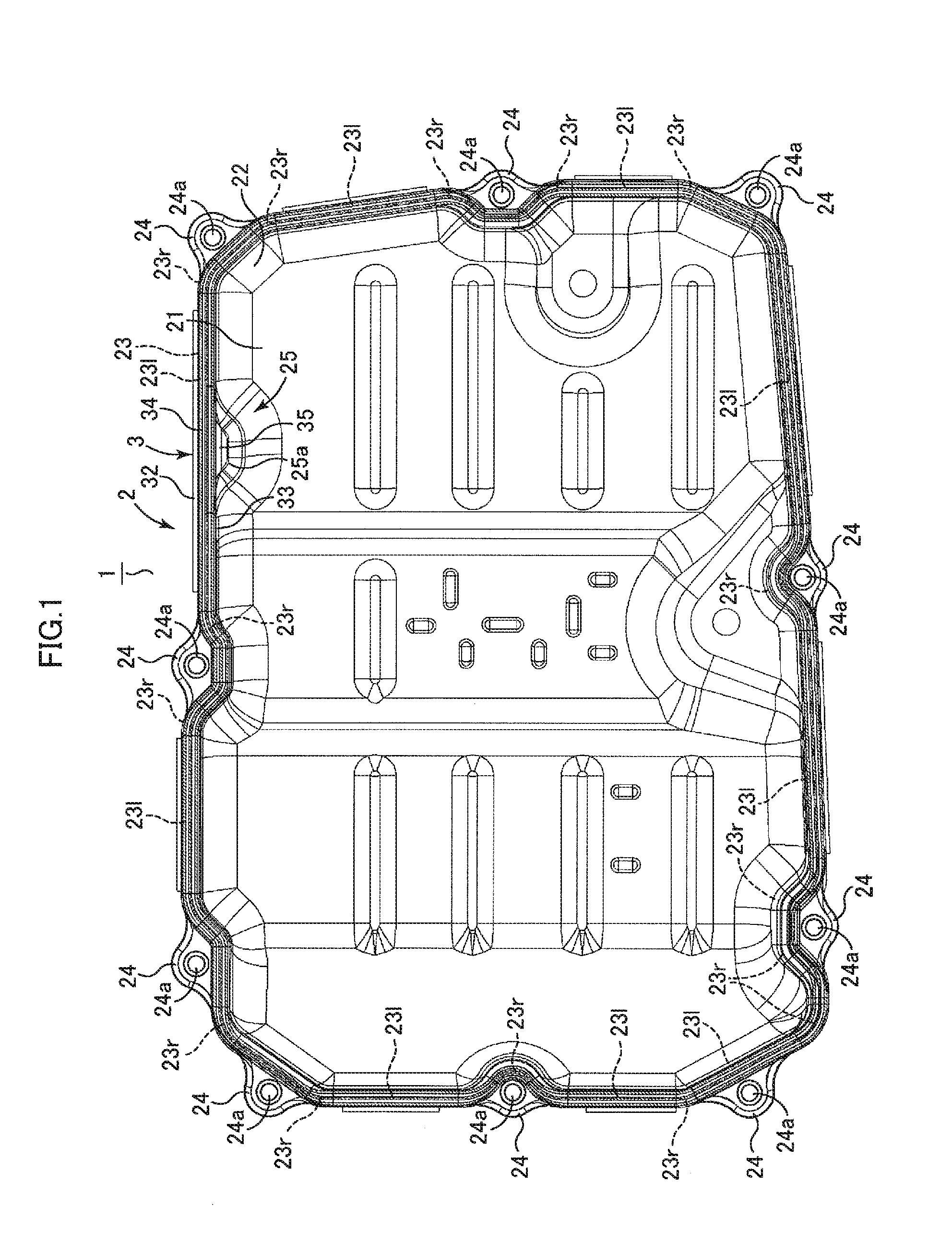
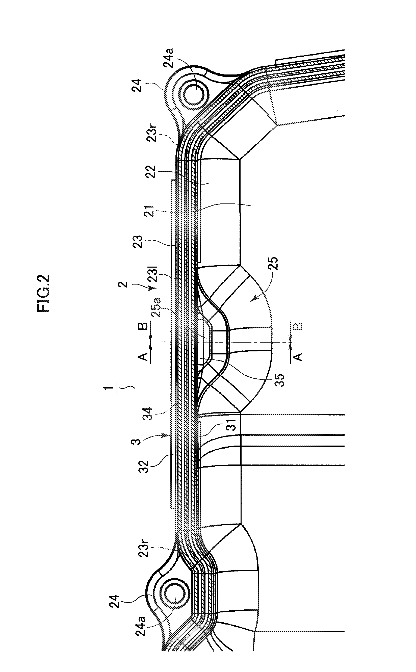
[0021]As illustrated in FIG. 1, the sealing-equipped oil pan 1 of this embodiment includes an oil pan 2 and a gasket (sealing member) 3 provided to the oil pan. The oil pan 2 is fastened to a transmission case 40 (see FIG. 4) of an automatic transmission 4 using bolts (not shown) with the gasket 3 interposed between the oil pan 2 and the transmission case 40.

[0022]The oil pan 2 includes a bottom portion 21, a peripheral wall 22 standing upward from the periphery of the bottom portion 21, and a rim portion 23 having a ring shape when vi...


PUM


Abstract

A sealing-equipped oil pan includes a gasket and an oil pan having a bottom portion and a peripheral wall for storing oil, and a ring-shaped rim portion located at an end of the peripheral wall and provided with the gasket, and is fastened to a target device with the gasket interposed between the rim portion and the target device. The gasket has a projection projecting from a sealing surface configured to come into contact with the target device for sealing. The peripheral wall of the oil pan has a base portion projecting from the rim portion and supporting the projection of the gasket. The base portion supports the projection of the gasket to prevent the gasket from tilting with respect to the rim portion, thereby preventing protrusion of the gasket.

Description

TECHNICAL FIELD[0001]The present art relates to an oil pan equipped with sealing that is fastened to a device such as an automatic transmission, a hybrid drive device, or an engine and encloses and stores oil to be circulated.BACKGROUND ART[0002]In general, a device such as an automatic transmission, a hybrid drive device, or an engine that is mounted in a vehicle is subjected to lubrication and cooling using oil and, depending on the configuration of a device, to hydraulic control using oil. To collect and store oil used for such purposes, an oil pan is provided below the device, for example. The oil pan is attached to the device in such a manner that a gasket made of rubber or the like for sealing oil is interposed between the oil pan and the device, and the oil pan is fastened to the device with a plurality of bolts (see Patent Document 1).RELATED-ART DOCUMENTSPatent Documents[0003][Patent Document 1] Japanese Patent Application Publication No. 2005-188533 (JP 2005-188533 A)SUMMA...

Claims


Application Information

Patent Timeline
IPC IPC(8): F01M11/00F16J15/06
CPCF02F11/00F01M11/0004F01M2011/0054F01M2011/0062F16J15/062F01M2011/0058F16J15/061
Inventor MIZOGUCHI, YASUHIROSAIKI, TOSHIAKIIWASE, MIKIO
Owner AISIN AW CO LTD
Why Eureka
Try Eureka