Driven wheel assembly and automotive vehicle equipped with such an assembly

Active Publication Date: 2016-08-04
VOLVO LASTVAGNAR AB
View PDF1 Cites 3 Cited by
  • Summary
  • Abstract
  • Description
  • Claims
  • Application Information

AI Technical Summary

Benefits of technology

[0007]Thanks to an aspect of the invention, the tubular portion of the brake disc can have a reduced length, impr

Problems solved by technology

In addition, in the case where some types of wheels, which are relatively large, are mounted on the vehicl

Method used


Image

  • Driven wheel assembly and automotive vehicle equipped with such an assembly
  • Driven wheel assembly and automotive vehicle equipped with such an assembly
  • Driven wheel assembly and automotive vehicle equipped with such an assembly

Examples


first embodiment

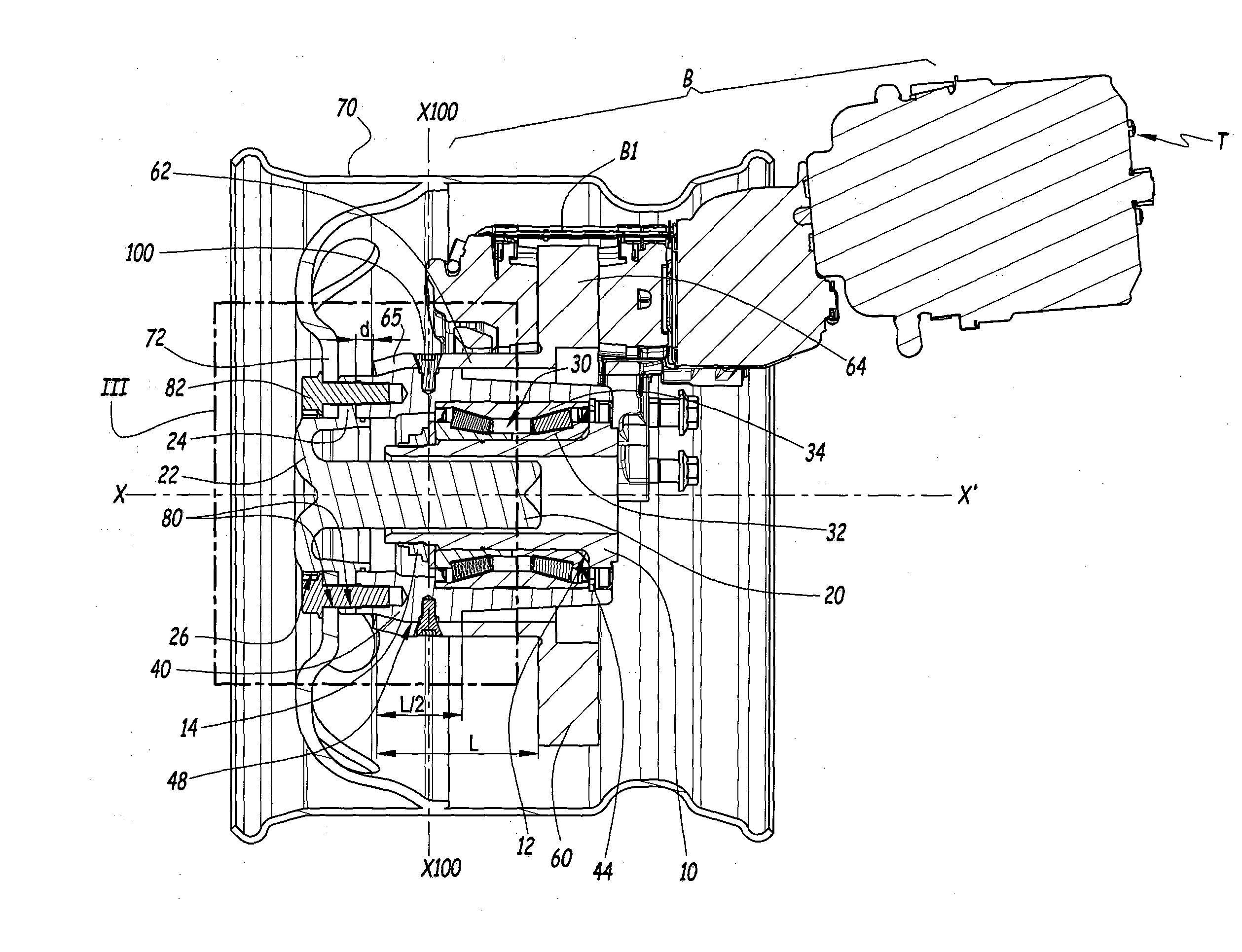
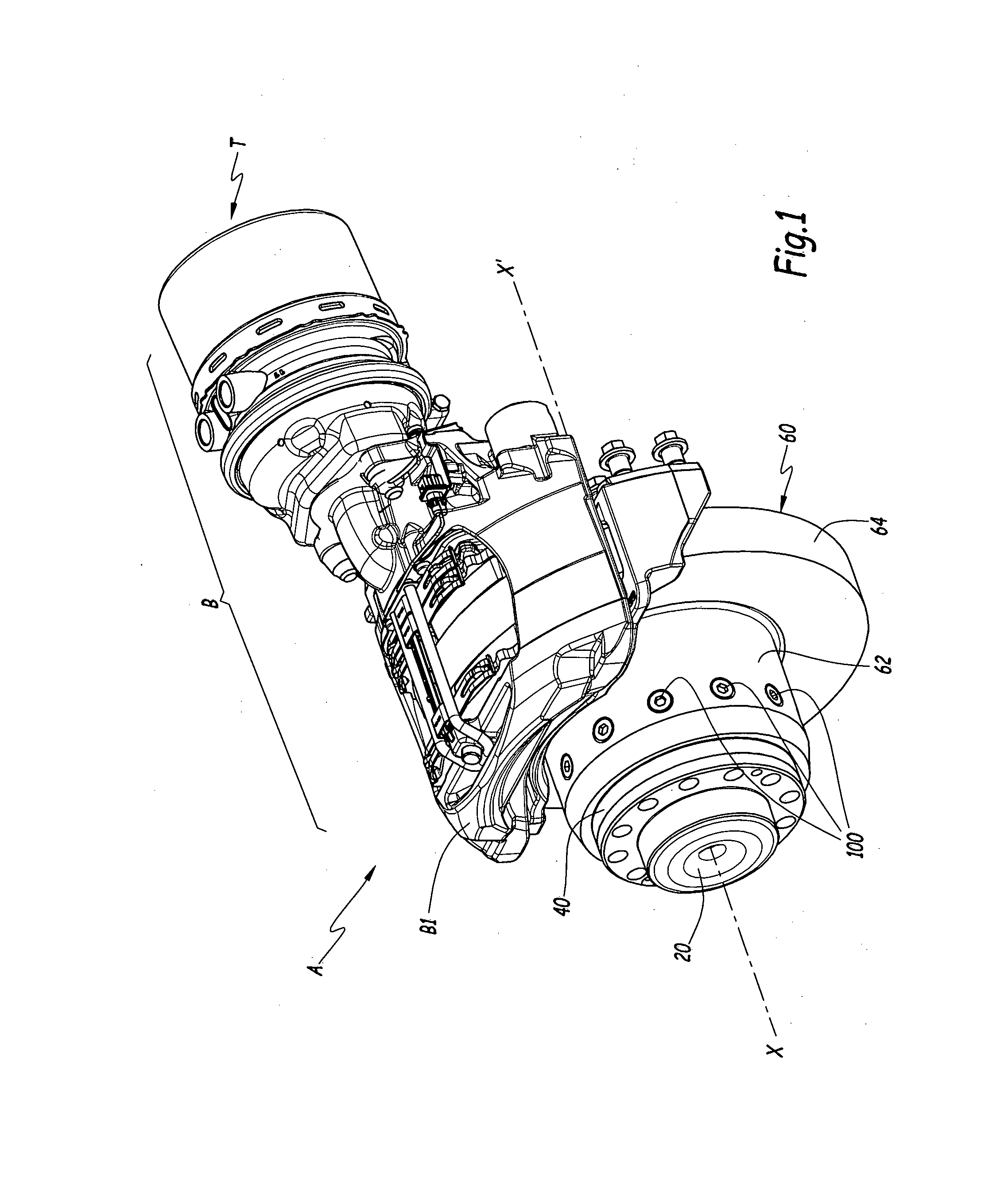
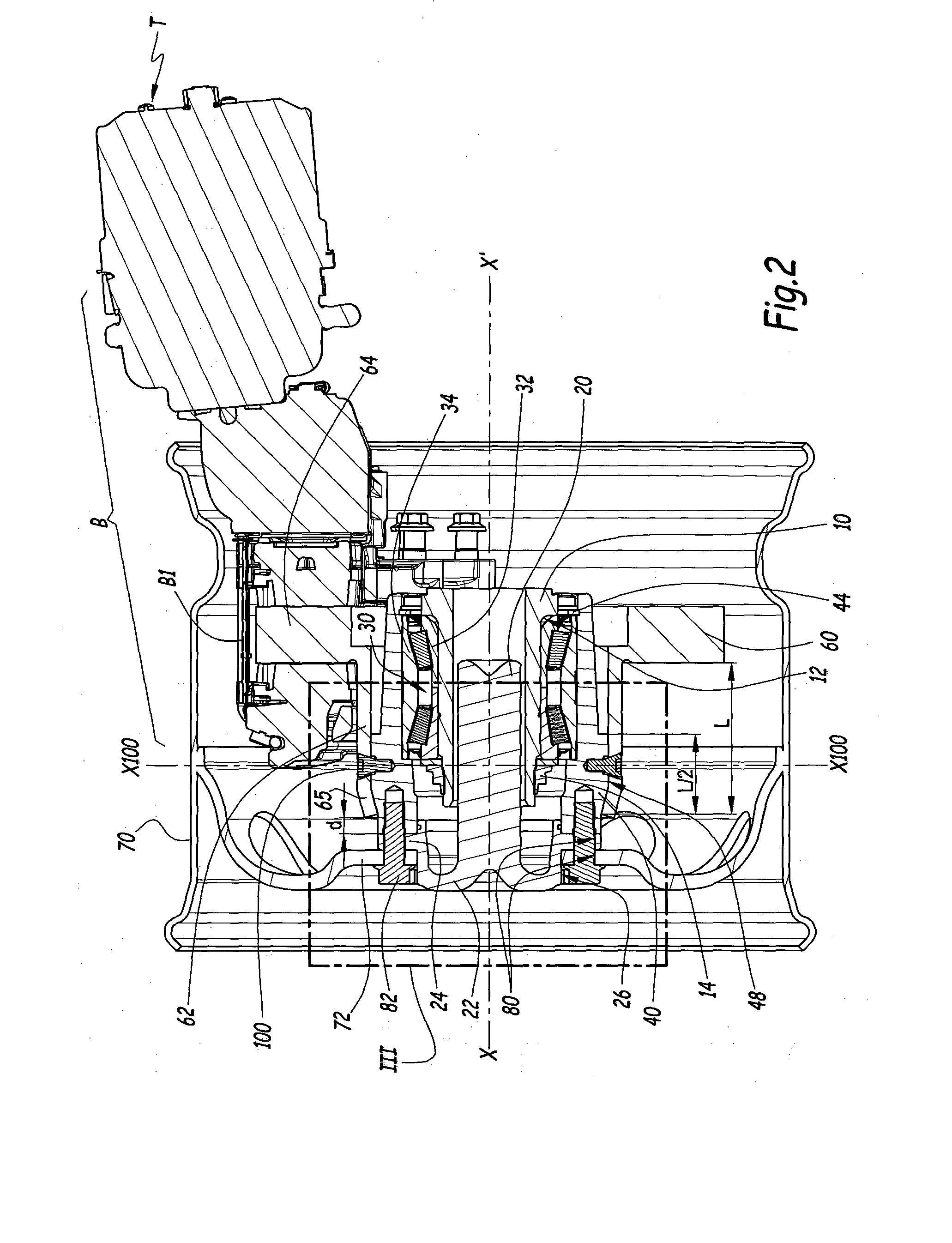
[0050]To this end and in the invention represented on FIGS. 1 to 3, hub 40 may comprise a first frustoconical surface 49 which extends from cylindrical surface 48 towards wheel rim 70. On its axial end 65 opposed to friction part 64, tubular portion 62 may be provided with a second frustoconical surface 620 which converges towards axis X-X′ opposite from friction part 64. The first frustoconical surface 49 has a corresponding shape with the second frustoconical surface 620. The second frustoconical surface 620 is mounted against the first frustoconical surface 49.

[0051]The friction elements also comprise means to urge surfaces 620 and 49 against each other in order to generate friction between surfaces 620 and 49. According to the first embodiment of the invention represented on FIGS. 1 to 3, the means to urge surfaces 620 and 49 against each other can be realized by tapered surfaces of the heads 102 of screws 100 and corresponding tapered surfaces 622a of holes 622. As represented ...

second embodiment

[0054]In this second embodiment, assembly A comprises wedges 120 inserted in tubular portion 62 and in which radial screws 100 are inserted along axis X100. Each wedge 120 comprises a lateral surface 122 oriented towards the inner side of assembly A. Lateral surface 122 is inclined with respect to axis X100 and converges towards this axis opposite from head 102 of each screw 100.

[0055]Wedges 120 are inserted in holes 624 of tubular portion 62, which have, for instance, a substantially square shape. Holes 624 have an inner surface 624a which faces lateral surface 122 and is parallel to lateral surface 122. Lateral surface 122 and inner surface 624a are in sliding contact when screws 100 are screwed in bores 48a.

[0056]The cooperation between surfaces 122 and 624a forms the means to urge surfaces 49 and 620 against each other and generates a force F2 exerted on tubular portion 62 and oriented, along axis X-X′ towards the inner side of assembly A. Force F2 tends to move brake disc 60 t...

third embodiment

[0063]Besides, radial pins 130 can be used in close cooperation with radial screws 100. For instance, in a third embodiment represented on FIG. 6, radial pins 130 are hollow, for instance of tubular shape, and are passed through by the radial screws 100. When screwed in threaded bores 48a, the radial screws 100 fasten the radial pins 130 on the hub 40.

[0064]According, to another non-shown embodiment of the invention, assembly A may comprise splines, polygonal surfaces or keys to couple in rotation brake disc 60 to hub 40 in order to reduce the shear strain sustained by radial screws 100.


PUM


Abstract

A driven wheel assembly includes a fixed axle spindle, a rotating drive shaft extending inside the axle spindle, a bearing, a hub, a brake disc, and a wheel rim. An inner ring of the bearing is mounted on the spindle. The hub is mounted on an outer ring of the bearing. The drive shaft, the brake disc and the wheel rim are coupled in rotation with the hub. The brake disc includes a radial friction part and a tubular portion which is fastened to the hub. The brake disc is fastened to the hub by a radial fastener extending along radial directions with respect to a rotation axis of the assembly and mounted through the tubular portion of the brake disc.

Description

BACKGROUND AND SUMMARY[0001]The present invention relates to a driven wheel assembly. More particularly, the present invention relates to a driven wheel assembly comprising an axle spindle, a rotating drive shaft, a bearing, a hub, a brake disc and a wheel rim. The invention also concerns an automotive vehicle, such as a truck, equipped with such a driven wheel assembly.[0002]Known driven wheel assemblies for vehicles, particularly large commercial vehicles, are provided with a drive shaft, a wheel rim and a brake disc coupled in rotation to a hub which rotates with respect to a fixed axle spindle via bearings.[0003]It is known from WO-A-2011 / 070387 to fasten the drive shaft, the brake disc and the wheel rim to the hub by a single set of screws which axially pass through respective fastening flanges of the drive shaft, the brake disc and the wheel rim. This solution implies that a relatively high number of parts are fastened by the same screws in the same area.[0004]In addition, in ...

Claims


Application Information

Patent Timeline
IPC IPC(8): F16D65/12B60B27/06B60B27/00F16C35/063B60B35/18B60B35/12
CPCB60B27/001B60B27/02B60B35/121B60B35/18F16C35/063F16D2065/1392F16D2065/1384B60B27/0021B60B27/065F16C2326/02F16D2065/136F16D65/123F16C19/386
Inventor DESSAINT JEAN, NICOLAS
Owner VOLVO LASTVAGNAR AB
Why Eureka
Try Eureka