
Laser Positioning System

a laser positioning system and positioning system technology, applied in the direction of optical conversion of sensor output, distance measurement, instruments, etc., can solve the problems of inability to employ mathematical techniques, render a laser based measurement system inoperable, and many existing laser based systems that cannot accommodate external disturbances or movements

Active Publication Date: 2016-08-04
CONSTR ROBOTICS
View PDF21 Cites 15 Cited by
  • Summary
  • Abstract
  • Description
  • Claims
  • Application Information

AI Technical Summary

Benefits of technology

The present invention relates to a laser positioning system comprising a laser line beacon positioning system and a target story pole. The system includes a laser line receiver that is coupled to a moveable assembly for intercepting laser light from the positioning system, providing a reference for accurate moveable assembly motion. The technical effect of the invention is to provide a reliable and accurate system for positioning and guiding moveable assemblies in construction projects.

Problems solved by technology

Many of these existing laser based systems do not accommodate external disturbances or movement.
The precise nature of a laser beam is very useful in measurement systems, but also presents a problem when the external environment contains movement or disturbances.
One example of an environmental disturbance that renders a laser based measurement system inoperable is that of fog or rain.
While disturbance compensation using mathematical techniques to remove the disturbance empirically can be adapted to such situations, and stabilization techniques to reduce or eliminate the disturbance can also he used, oftentimes the disturbance is such that it either cannot be entirely stabilized through mechanical means, or the movement is such that the laser beam does not hit its intended sensing or receiving target and mathematical techniques cannot be employed without received data from an incident laser hit.

Method used


Image

  • Laser Positioning System
  • Laser Positioning System
  • Laser Positioning System

Examples


Embodiment Construction

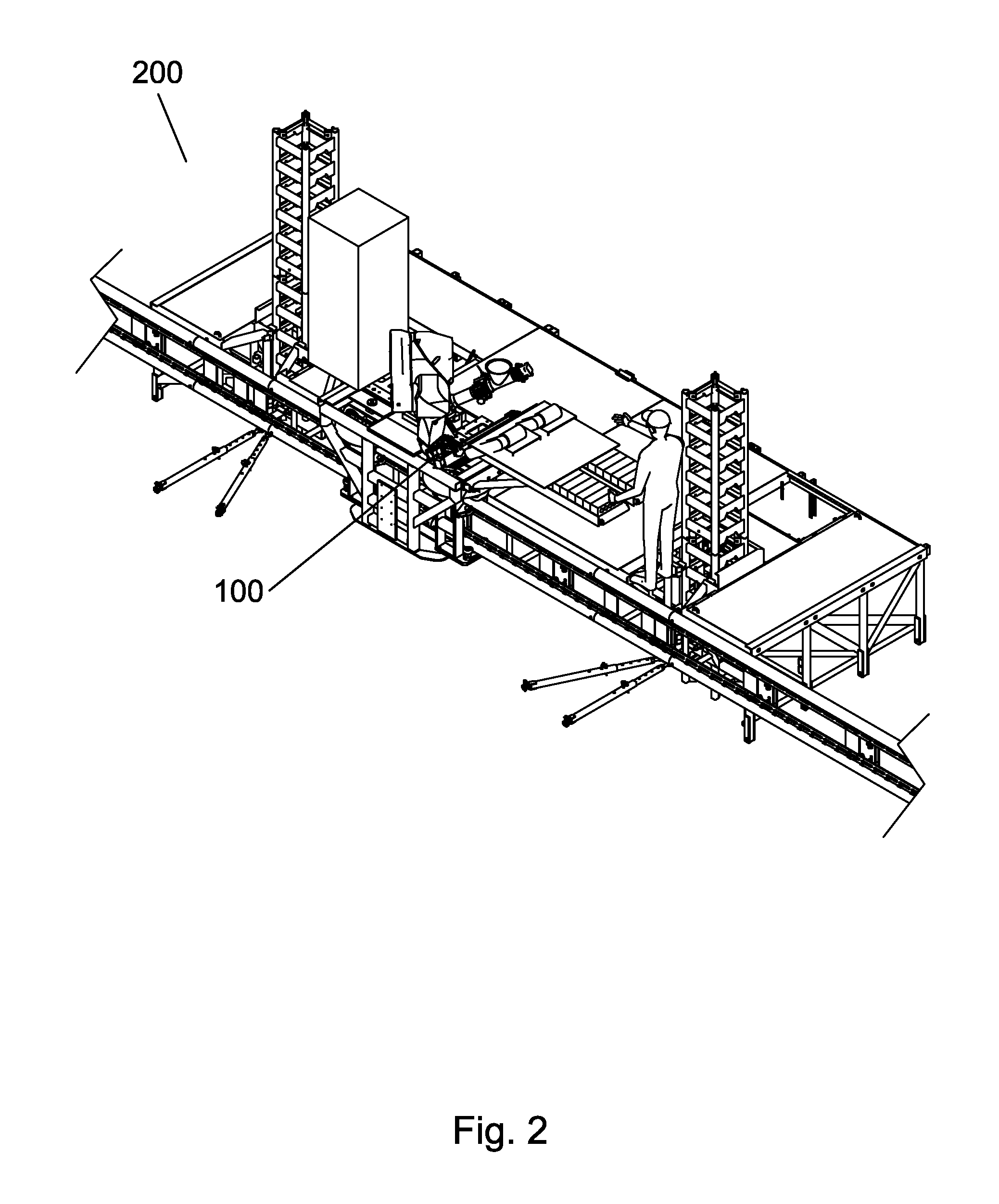
[0058]The laser positioning system of the present invention provides a positioning and guidance system that is suitable for environments that have external disturbances such as those caused by wind, equipment movement, vibration, and the like. Exemplary applications of the laser positioning system include, but are not limited to, accurate positioning of bricks in a wall under construction by a robotic brick laying system. An example of such a robotic brick laying system is described in United States Patent Application Publication US2012 / 0053726 A1 to Peters et al. and entitled “Brick Laying System”, the entire disclosure of which is incorporated herein by reference in its entirety.

[0059]The laser positioning system of the present invention uses a novel arrangement of a laser line beacon positioning system in optical communication with a laser line receiver to achieve accurate positioning in environments with external disturbances, something that has previously not been attainable. W...


PUM


Abstract

A laser positioning system is described. The laser positioning system provides a positioning and guidance system that is suitable for environments that have external disturbances such as those caused by wind, equipment movement, vibration, and the like. The laser positioning system of the present invention uses at novel laser line beacon positioning system in optical communication with a novel laser line receiver to achieve accurate positioning in environments with external disturbances, something that has previously not been attainable. In some embodiments, a target or series of targets are used to create a reference by which the laser line receiver and an associated moveable assembly such as a robotic arm assembly are able to accurately place building elements such as bricks. Exemplary applications of the laser positioning system include, but are not limited to, accurate positioning of bricks in a wall under construction by a robotic brick laying system.

Description

CROSS REFERENCE TO RELATED PATENT APPLICATIONS[0001]This application claims priority to U.S. patent application Ser. No. 62 / 109,600 filed Jan. 29, 2015 entitled “Laser Positioning System” by Scott Lawrence Peters et al., the entire disclosure of which is incorporated herein by reference.BACKGROUND OF THE INVENTION[0002]1. Field of the Invention[0003]The present invention relates generally to positioning systems, and more particularly to a Laser Positioning System that defines the absolute position of an element under the influence of external disturbances.[0004]2. Description of the Related Art[0005]Positioning systems are useful for many applications where elements are placed, assembled, moved, re-oriented, or otherwise positioned. Sensing and measuring systems have in recent years made extensive use of lasers and related equipment to determine distance, create a straight line, and the like. There has been a proliferation in the construction trade (as well as other fields of endeav...

Claims


Application Information

Patent Timeline
IPC IPC(8): G01D5/26G01C3/08
CPCG01C3/08G01D5/26G01C15/004G01D5/305
Inventor PETERS, SCOTT LAWRENCEWHITE, GLENN DAYTONYARID, ROCKWELL NAJEEBALLMANN, ERWIN LUDWIGVOORHEIS, TIMOTHY RILEY
Owner CONSTR ROBOTICS
Learn More