Electromagnetic relay

Active Publication Date: 2016-08-04
ANDEN CORP
View PDF7 Cites 10 Cited by
  • Summary
  • Abstract
  • Description
  • Claims
  • Application Information

AI Technical Summary

Benefits of technology

[0019]According to the above configuration, because the number of components involved

Problems solved by technology

This makes it difficult to sufficiently increase opposed areas of the movable core and the fix

Method used


Image

  • Electromagnetic relay
  • Electromagnetic relay
  • Electromagnetic relay

Examples


Example

First Embodiment

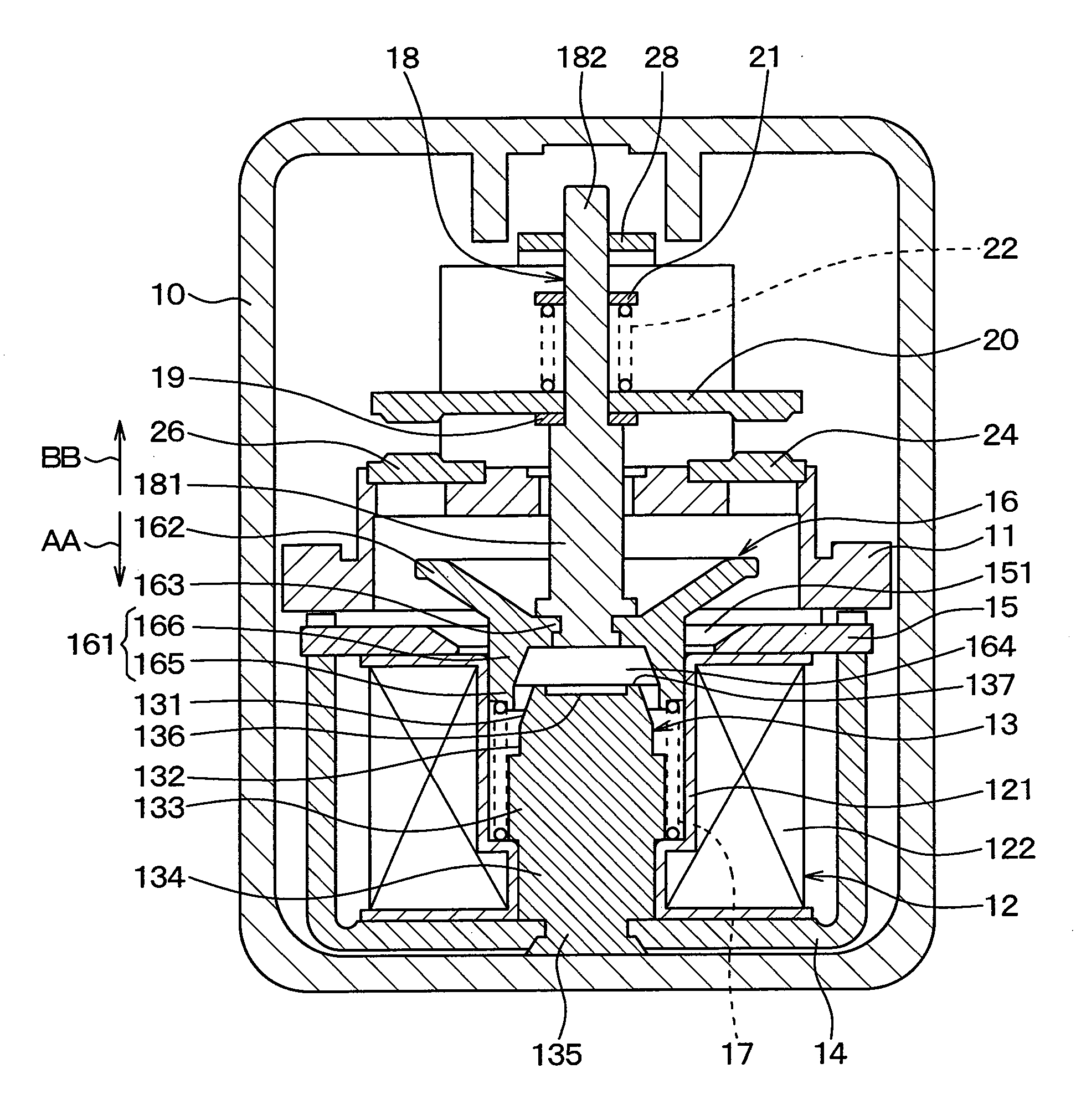
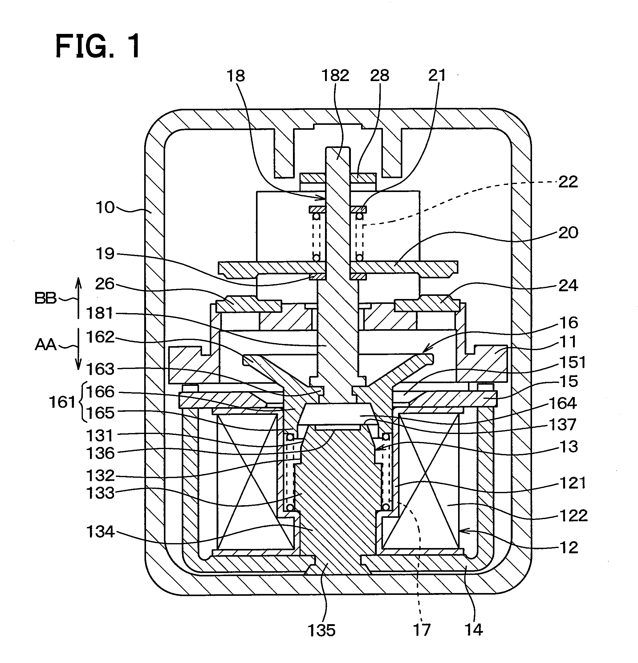
[0023]A first embodiment is described.

[0024]In the following description, a way of moving a movable core 16 by starting the energization of an exciting coil 12 is called “attraction direction AA”, and a way of moving the movable core 16 by blocking the energization of the exciting coil 12 is called “non-attraction direction BB”. The attraction direction AA and the non-attraction direction BB are called “moving direction of movable core” together. The non-attraction direction BB is also called “anti-attraction direction” or “release direction”, and means a direction opposite to the attraction direction AA in the moving direction of the movable core.

[0025]As illustrated in FIG. 1, a base 11 that is made of resin is disposed within a case 10 made of resin, and holds components. The base 11 is fixed to the case 10 by adhesive or fitting such as claw.

[0026]The exciting coil 12 having a cylindrical shape and generating a magnetic field during the energization is disposed w...

Example

Second Embodiment

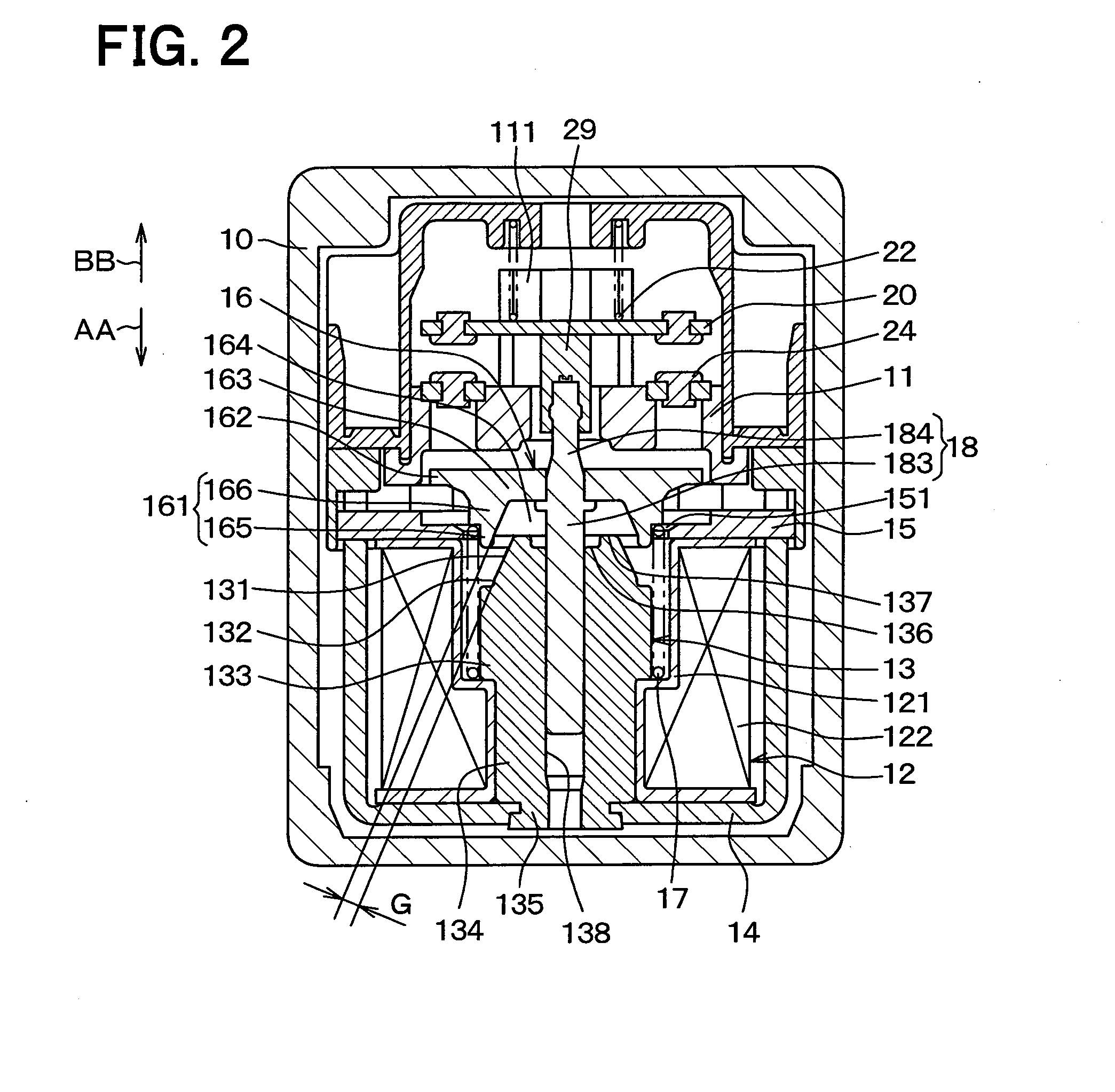
[0061]Next, a second embodiment will be described. This embodiment enables to reduce a variation in an air gap, and hereinafter only parts different from those in the first embodiment will be described.

[0062]In this embodiment, the second snap ring 21 and the support member 28 in the first embodiment are eliminated.

[0063]As illustrated in FIG. 2, a fixed core hole 138 extending in an axial direction of a fixed core 13 is defined at a radial center of the fixed core 13, and the fixed core 13 is formed into a substantially cylindrical shape.

[0064]In a movable core 16, a surface of a movable core flange part 162 in a non-attraction direction BB is made flat.

[0065]A shaft 18 includes a shaft third cylindrical portion 183 extending from a coupling position with the movable core 16 in an attraction direction AA, and a shaft fourth cylindrical portion 184 extending from the coupling position with the movable core 16 in the non-attraction direction BB.

[0066]The shaft third ...


PUM


Abstract

A fixed core includes: a fixed core tapered portion having a diameter increased in an attraction direction; and a fixed core circular portion having a fixed outer diameter and extending in the attraction direction from an end of the fixed core tapered portion. A movable core includes a movable core tubular portion in which a movable core hole is defined. The movable core hole is a space into which the fixed core tapered portion and the fixed core circular portion can enter. The movable core tubular portion includes: a movable core cylindrical portion having a constant inner diameter; and a movable core tapered tubular portion having an inner diameter decreased from an end of the movable core cylindrical portion in a non-attraction direction.

Description

CROSS REFERENCE TO RELATED APPLICATIONS[0001]This application is based on Japanese Patent Application No. 2013-194120 filed on Sep. 19, 2013 and Japanese Patent Application No. 2014-128252 filed on Jun. 23, 2014, the disclosures of which are incorporated herein by reference.TECHNICAL FIELD[0002]The present disclosure relates to an electromagnetic relay that opens or closes en electric circuit.BACKGROUND ART[0003]Up to now, one of the electromagnetic relays of this type is disclosed in, for example, Patent Literature 1. The electromagnetic relay disclosed in Patent Literature 1 is configured so that an electromagnetic attraction force is generated between opposed surfaces of a movable core formed of a plate and a fixed core formed of a plate due to the energization of an exciting coil. The movable core is attracted toward the fixed core due to the electromagnetic attraction force.[0004]The opposed surfaces of the movable core and the fixed core are inclined with respect to a moving d...

Claims


Application Information

Patent Timeline
IPC IPC(8): H01H50/20H01H50/60H01H50/56H01H50/36
CPCH01H50/16H01H50/20H01H50/60H01H50/36H01H50/56H01H50/163
Inventor SUGISAWA, MASANAOITO, TAKASHIKAMIYA, MAKOTOFUJIWARA, MITSUGUTANAKA, TOMOAKI
Owner ANDEN CORP
Why Eureka
Try Eureka