Lamp heating for process chamber

a technology of process chambers and lamps, which is applied in the direction of lighting and heating apparatus, drying, furnaces, etc., can solve the problems of hundreds or thousands of lamps, non-uniform temperature control around the different angular locations of the substrate, and inconvenient us

Active Publication Date: 2016-08-04
APPLIED MATERIALS INC
View PDF13 Cites 6 Cited by
  • Summary
  • Abstract
  • Description
  • Claims
  • Application Information

AI Technical Summary

Benefits of technology

[0065]The embodiments described herein illustrate lamp arrangements for use in process chambers that can substantially reduce manufacturing costs as well as maintenance costs for the lamphead. The cost savings is achieved by reducing the number of lamps needed in the lamphead. Less lamps require less wiring and less time to mount in the lamphead. Furthermore, less lamps will result in less frequent replacement of lamps resulting in less downtime and maintenance. For example, some lampheads for process chambers include over 400 lamps or even greater than 1,000 lamps. Lamps eventually fail, so operating a process chamber with over 400 lamps will likely require replacing thousands of lamps over the useful life of the lamphead. In many of the embodiments described above, the number of lamps can be maintained below 100 lamps.

Problems solved by technology

While these arrangements can provide adequate temperature control of radial locations on the substrates being processed, the temperature control around the different angular locations of the substrate still suffers from non-uniformities.
Other arrangements, such as a honeycomb arrangement having hundreds or even thousands of lamps can provide improved temperature control, but having hundreds or thousands of lamps is not a cost-effective solution.

Method used


Image

  • Lamp heating for process chamber
  • Lamp heating for process chamber
  • Lamp heating for process chamber

Examples


Embodiment Construction

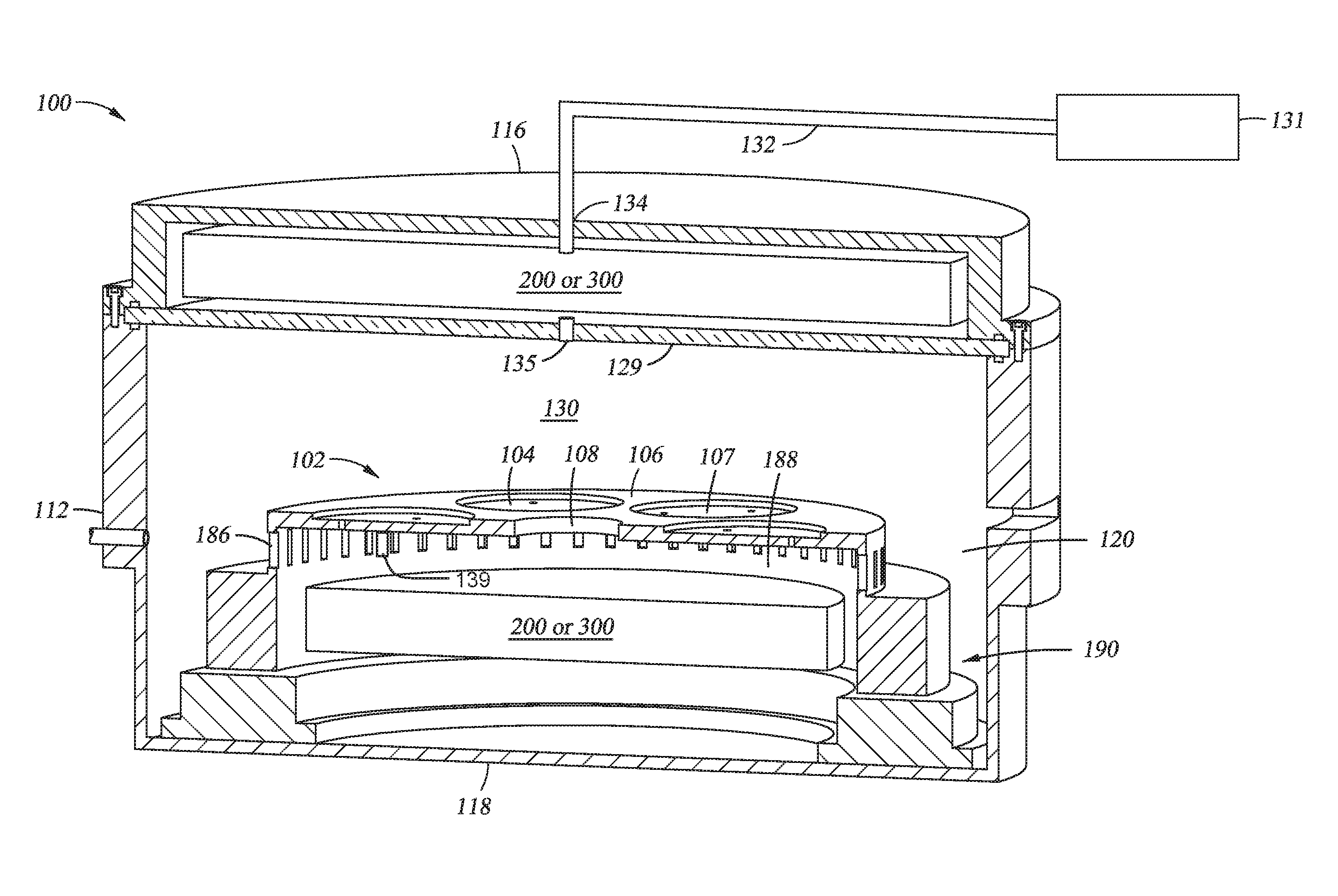
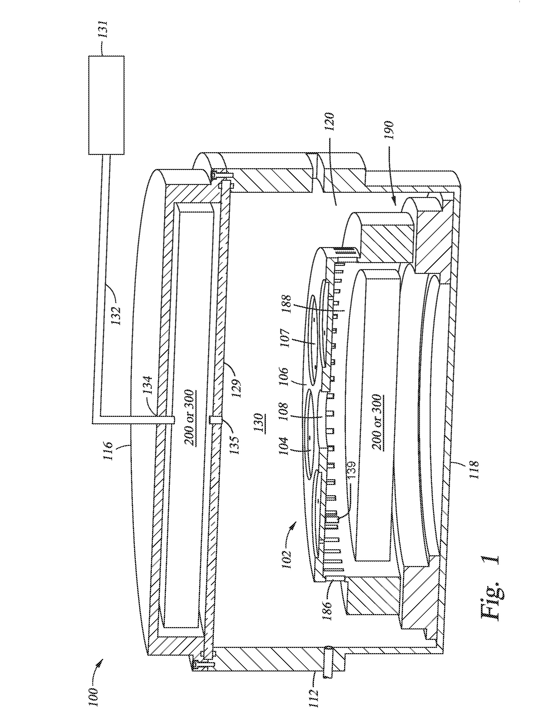
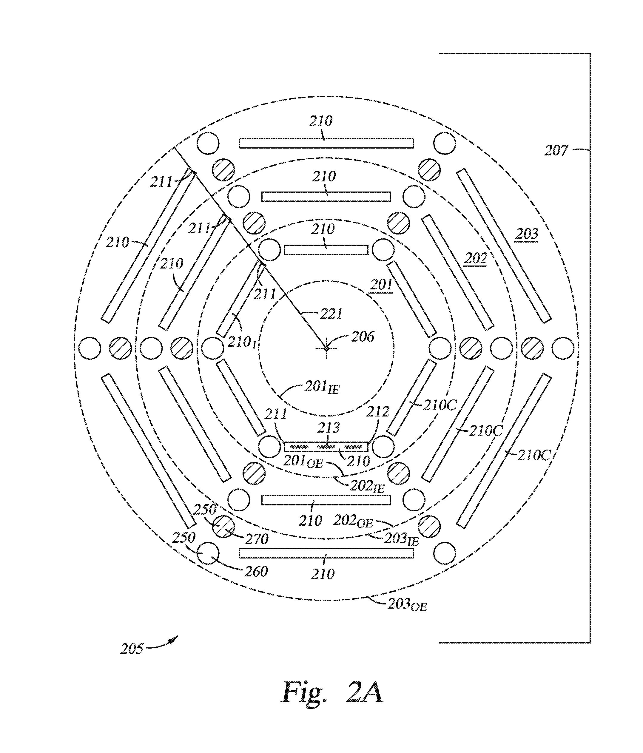
[0018]The present disclosure relates generally to lamp heating of process chambers used to process semiconductor substrates. More specifically, embodiments disclosed herein are related to arrangements of linear lamps for heating of semiconductor substrates.

[0019]In this disclosure, the terms “top”, “bottom”, “side”, “above”, “below”, “up”, “down”, “upward”, “downward”, “horizontal”, “vertical”, and the like do not refer to absolute directions. Instead, these terms refer to directions relative to a basis plane of the chamber, for example a plane parallel to a substrate processing surface of the chamber. Furthermore, because this application discloses lampheads 200 and 300 that may be provided above or below a substrate support, any specific example given for a lamphead or lamp arrangement above the substrate support should be understood by the reader to also include a similar or mirror image lamphead or lamp arrangement below the substrate support without specific recitation of that ...


PUM


Abstract

A process chamber is provided including a top, a bottom, and a sidewall coupled together to define a volume. A substrate support is disposed in the volume. The process chamber further includes one or more lampheads facing the substrate support, each lamphead comprising an arrangement of lamps disposed along a plane. The arrangement of lamps is defined by a center and a plurality of concentric ring-shaped zones. Each ring-shaped zone is defined by an inner edge and an outer edge and each ring-shaped zone includes three or more alignments of one or more lamps. Each alignment of one or more lamps has a first end extending linearly to a second end that are separated by at least 10 degrees around the center. The first end and the second end are both located within one ring-shaped zone. Each alignment located within a same ring-shaped zone is equidistant to the center.

Description

CROSS-REFERENCE TO RELATED APPLICATIONS[0001]This application claims benefit of U.S. provisional patent application Ser. No. 62 / 110,440, filed Jan. 30, 2015 and U.S. provisional patent application Ser. No. 62 / 141,133, filed Mar. 31, 2015, which are both hereby incorporated herein by reference.BACKGROUND[0002]1. Field[0003]Embodiments disclosed herein generally relate to lamp heating of process chambers used to process semiconductor substrates. More specifically, embodiments disclosed herein are related to arrangements of linear lamps for heating of semiconductor substrates.[0004]2. Description of the Related Art[0005]Various processes are used to form electronic devices on semiconductor substrates. Such processes include chemical vapor depositions, plasma enhanced chemical vapor depositions, atomic layer depositions, and epitaxy. These processes are performed in process chambers, and temperature control across the surface of the semiconductor substrate disposed within the process ch...

Claims


Application Information

Patent Timeline
Patent Type & Authority Applications(United States)
IPC IPC(8): H05B3/00F26B3/30
CPCF26B3/30H05B3/0047H01L21/67115
Inventor SAMIR, MEHMET TUGRULCHU, SCHUBERT S.
Owner APPLIED MATERIALS INC
Why Eureka
Try Eureka