Robot, control method, and program

a control method and robot technology, applied in the field of robots and control methods, can solve the problems of hard robots to detect the face of people from the image of the surroundings, and wrongly detecting the face in the picture as the face of real people, so as to increase the probability, increase the probability, and increase the probability of a person's head

Active Publication Date: 2016-08-11
NEC CORP
View PDF2 Cites 6 Cited by
  • Summary
  • Abstract
  • Description
  • Claims
  • Application Information

AI Technical Summary

Benefits of technology

[0044]As mentioned above, the robot 2000 of the present exemplary embodiment detects a temperature distribution of a detection region by using the temperature distribution detection unit 2040, and detects a direction in which a person's head is located on the basis of the detected temperature distribution. In addition, a direction of the face unit 2020 is changed to the direction of the detected direction of a person's face. The robot 2000 detects the direction in which the person's head is located by using the temperature distribution and can thus detect the direction in which the person's head is located regardless of whether the person's head is directed toward the robot 2000. Therefore, according to the robot 2000 of the present exemplary embodiment, it is possible to detect a direction in which a person's head is located even if a person's face is not directed toward the robot 2000 unlike in the method of detecting a person's face from an image. Thus, according to the robot 2000 of the present exemplary embodiment, the face unit 2020 can be directed in a direction in which a person's head is located with high probability, and thus it is possible to increase a probability that the person and the robot 2000 can perform natural communication with each other.
[0045]Here, a direction in which a person's head is located and a direction in which a person's face is located can be said to be substantially the same as each other. In addition, generally, a person tends to be directed toward an object in response to the object being directed toward the person. For this reason, by directing the face unit 2020 of the robot 2000 toward the person's head, it is highly probable that the person's own face will be directed toward the face unit 2020 even if the face unit 2020 is not accurately directed toward the person's face. As a result, the person's face and the face unit 2020 are directed toward each other, and thus the person and the robot 2000 can perform natural communication with each other.
[0046]In addition, in a case of using a method of causing a person to be directed toward the robot 2000 by the robot outputting sound or the robot moving to the front of the person, the person may feel discomfort in communication with the robot or may feel forced to perform communication with the robot. Thus, from the person's viewpoint, such communication with the robot is not substantially natural communication. On the other hand, the robot 2000 of the present exemplary embodiment directs the face unit 2020 in a direction in which a person's head is located, and thus the person would voluntarily direct toward the robot 2000. Thus, there is a low probability that the person may feel discomfort in communication with the robot 2000 or feel forced to perform communication with the robot 2000. Therefore, according to the robot 2000 of the present exemplary embodiment, the robot 2000 and the person perform natural communication with each other.
[0048]The respective functional constituent units of the robot 2000 are implemented as at least a single hardware constituent element alone or in a state in which a plurality of functional constituent units are combined with each other. In addition, for example, the respective functional constituent units are implemented as at least a single software constituent element. Further, for example, each functional constituent unit may be implemented by a combination of a hardware constituent element and a software constituent element.
[0067]Here, an angle of a detection result of the temperature distribution detection unit 2040 may be less than 180 degrees (for example, 60 degrees). FIG. 5 shows diagrams illustrating states in which the detection region of the temperature distribution detection unit 2040 is viewed sideways in a horizontal direction. In a case where the temperature distribution detection unit 2040 is installed at a position which may be lower than a person's head (for example, a height of 50 cm from the ground), the temperature distribution detection unit 2040 is preferably installed with being tilted upward from the horizontal direction as illustrated in FIG. 5(b). On the other hand, in a case where the temperature distribution detection unit 2040 is installed at a position which may be higher than a person's head (for example, a height of 2.5 m from the ground), the temperature distribution detection unit 2040 is preferably installed with being tilted downward from the horizontal direction as illustrated in FIG. 5(c). As mentioned above, the temperature distribution detection unit 2040 is installed with being appropriately tilted, and thus it is possible to increase a probability that a person's head may be included in the detection region 10.
[0069]The number of temperature distribution detection units 2040 provided in the robot 2000 may be one or plural. If the number of temperature distribution detection units 2040 provided in the robot 2000 is reduced, costs for providing the temperature distribution detection units 2040 are reduced. On the other hand, if the number of temperature distribution detection units 2040 provided in the robot 2000 is increased, temperature distributions of a wide region can be detected even if a frequency of changing directions of the temperature distribution detection units 2040 is reduced. As a result, it is possible to delay deterioration of a driving portion used for an operation such as rotating the body.

Problems solved by technology

However, it is hard for such robots to detect a person's face and to therefore perform natural communication with the person.
For this reason, for example, if the person directs in a direction opposite to the robot, it is hard for the robot to detect the person's face from the image of the surroundings.
In addition, for example, if a picture of a person is captured in an image of the surroundings, such a robot may wrongly detect the face in the picture as a real person's face.
Further, if such a robot is located in a dark place, it is hard to detect a person's face from an image of the surroundings.
However, it may be hard for the human body detection apparatus to detect a person.
Thus, if a person has a low posture (for example, when the person crouches), the human body detection apparatus may not detect the person.

Method used


Image

  • Robot, control method, and program
  • Robot, control method, and program
  • Robot, control method, and program

Examples


exemplary embodiment 1

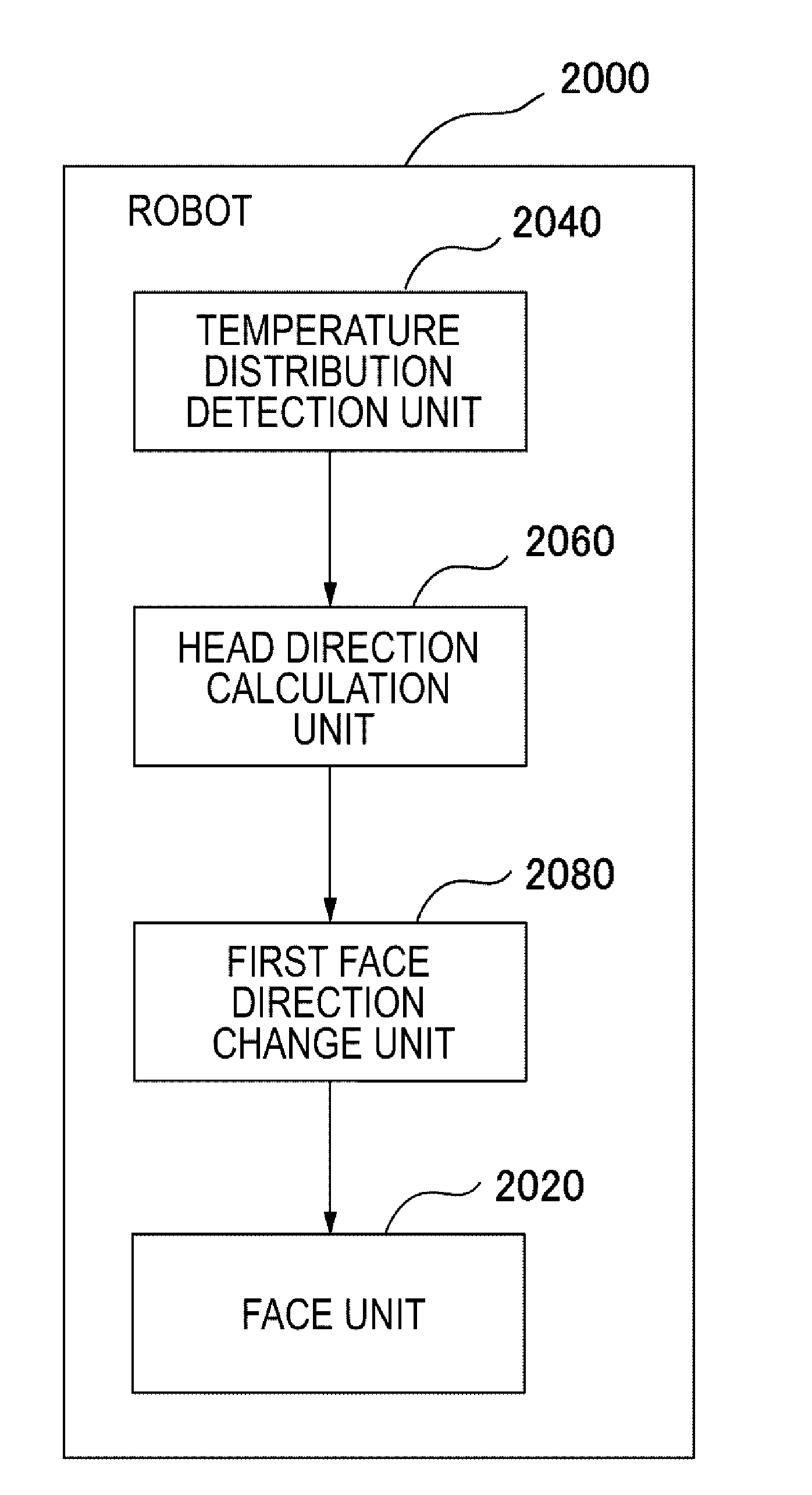
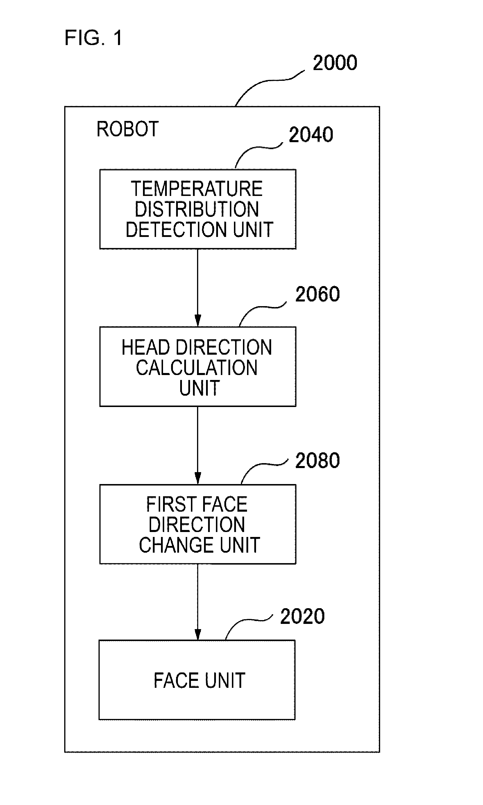
[0040]FIG. 1 is a block diagram illustrating a robot 2000 arrow indicates a flow of information. In addition, in FIG. 1, each block indicates not a configuration in the hardware unit but a configuration in the function unit.

[0041]

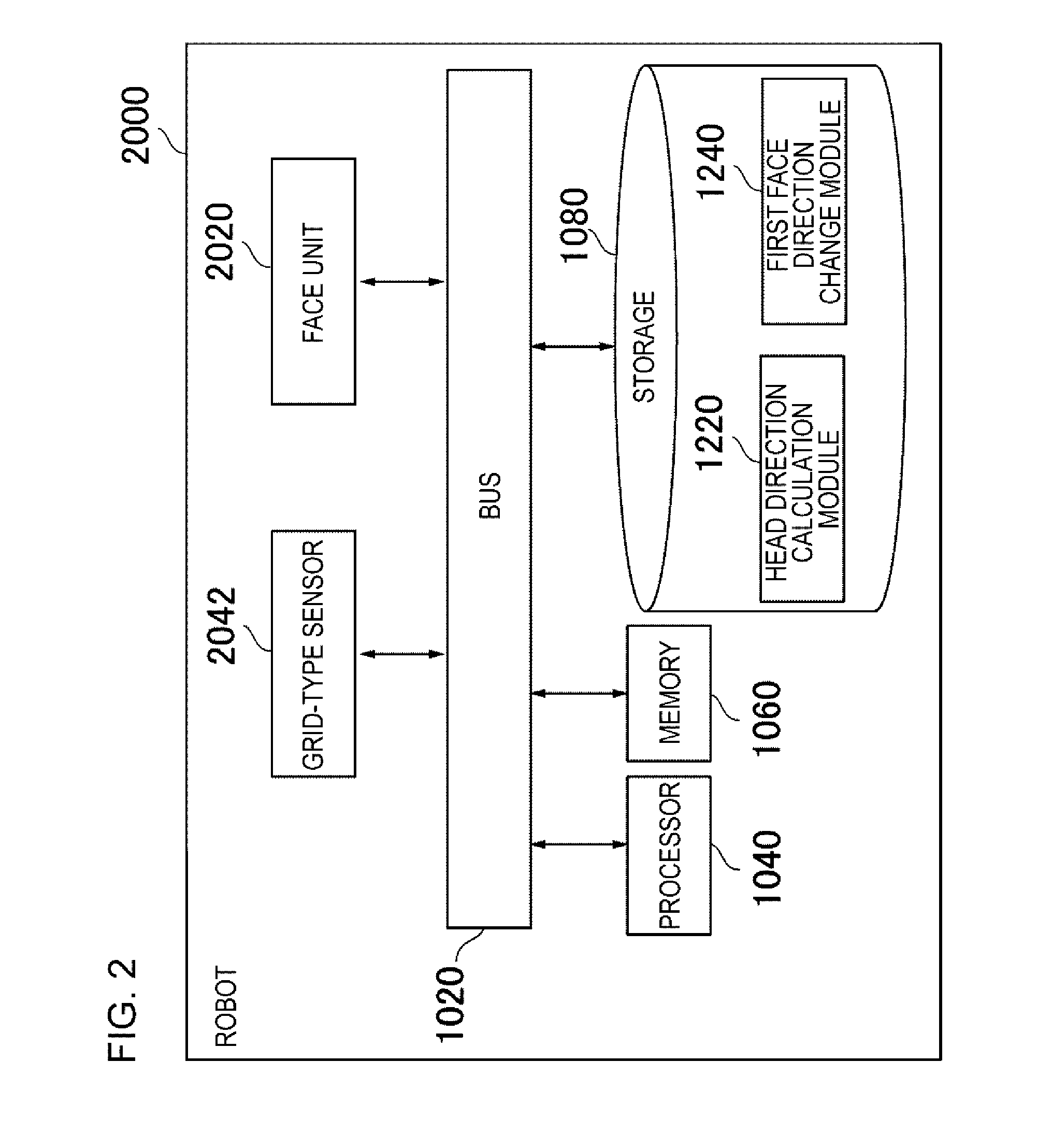
[0042]The robot 2000 includes a face unit 2020, a temperature distribution detection unit 2040, a head direction calculation unit 2060, and a first face direction change unit 2080. The temperature distribution detection unit 2040 includes a plurality of photo-detectors, which are disposed in a grid form. The temperature distribution detection unit 2040 detects a temperature distribution of a detection region by using the plurality of photo-detectors. The head direction calculation unit 2060 calculates a direction in which a person's head is located based on the temperature distribution detected by the temperature distribution detection unit 2040. The first face direction change unit 2080 directs the face unit 2020 in the direction calculated by the head dir...

exemplary embodiment 2

[0080]FIG. 6 is a block diagram illustrating a head direction calculation unit 2060 of a robot 2000 according to Exemplary embodiment 2. The robot 2000 according to the Exemplary embodiment 2 is the same as the robot 2000 according to the Exemplary embodiment 1 except that the head direction calculation unit 2060 includes respective functional constituent units illustrated in FIG. 6. In FIG. 6, an arrow indicates a flow of information. In addition, in FIG. 6, each block indicates not a configuration in the hardware unit but a configuration in the function unit.

[0081]The head direction calculation unit 2060 according to Exemplary embodiment 2 includes a reference temperature distribution storage unit 2061, a candidate position determination unit 2062, a head position determination unit 2063, and a direction calculation unit 2064.

[0082]2061>

[0083]The reference temperature distribution storage unit 2061 stores a reference temperature distribution. For example, the robot 2000 includes a...

exemplary embodiment 3

[0096]FIG. 8 is a block diagram illustrating a head direction calculation unit 2060 of a robot 2000 according to Exemplary embodiment 3. The robot 2000 according to the Exemplary embodiment 3 is the same as the robot 2000 according to the Exemplary embodiment 2 except that the head direction calculation unit 2060 includes respective functional constituent units illustrated in FIG. 8. In FIG. 8, an arrow indicates a flow of information. In addition, in FIG. 8, each block indicates not a configuration in the hardware unit but a configuration in the function unit.

[0097]The head direction calculation unit 2060 of Exemplary embodiment 3 has a function of updating the reference temperature distribution stored in the reference temperature distribution storage unit 2061. For this, the head direction calculation unit 2060 of Exemplary embodiment 3 includes a reference temperature distribution update unit 2065. Here, the temperature distribution detection unit 2040 of Exemplary embodiment 3 r...


PUM


Abstract

A robot (2000) includes a face unit (2020), a temperature distribution detection unit (2040), a head direction calculation unit (2060), and a first face direction change unit (2080). The temperature distribution detection unit (2040) includes a plurality of photo-detectors disposed in a grid form. The temperature distribution detection unit (2040) detects a temperature distribution of a detection region by using the plurality of photo-detectors. The head direction calculation unit (2060) calculates a direction in which a person's head is located, on the basis of the temperature distribution detected by the temperature distribution detection unit (2040). The first face direction change unit (2080) directs the face unit (2020) in the direction calculated by the head direction calculation unit (2060).

Description

TECHNICAL FIELD[0001]The present invention relates to a robot, a control method, and a program.BACKGROUND ART[0002]A robot performing communication with a person has been developed. For example, there is a nursing care robot or an education robot. Such a robot performs an operation such as “making a response to a request from a person with sound voice”.[0003]It is important for a robot performing communication with a person to perform natural communication without making the person feel uncomfortable. Therefore, a technique which enables a robot to perform natural communication with a person has been developed.[0004]In a robot disclosed in Patent Document 1, a person's face is detected from an image obtained by capturing the surroundings, and the eyes or a head of the robot is directed in a direction of the face so that communication is started.[0005]In a robot disclosed in Patent Document 2, a person's face is detected from an image obtained by capturing the surroundings, a degree ...

Claims


Application Information

Patent Timeline
Patent Type & Authority Applications(United States)
IPC IPC(8): B25J13/08B25J11/00
CPCB25J13/087B25J11/0015G01J5/0025
Inventor ISHIGURO, SHIN
Owner NEC CORP
Why Eureka
Try Eureka