Aircraft tail cone

a technology of tail cone and tail cone, which is applied in the direction of fuselage, inspection panel of power plants, transportation and packaging, etc., can solve the problems of limited access to equipment in the tail cone for inspection and/or maintenance operations, difficulty for operators to move around inside the tail cone, and little space left for persons to move freely

Inactive Publication Date: 2016-08-11
AIRBUS OPERATIONS (SAS) +2
View PDF8 Cites 23 Cited by
  • Summary
  • Abstract
  • Description
  • Claims
  • Application Information

AI Technical Summary

Benefits of technology

[0015]Most of this equipment is thus arranged in a region situated facing the lateral openings or in a region which is adjacent to this region and remains easily accessible from at least one of the openings.

Problems solved by technology

However, it is frequently difficult for the operators to move around inside the tail cone on account of the space taken up by the equipment and thus the little space that is left free for the movement of persons.
The accessibility of the equipment in the tail cone to operators for inspection and / or maintenance operations is thus greatly limited.
As a result, inspection and / or maintenance operations take time.
The difficulty of access also increases the risk of the equipment being damaged during maintenance operations.

Method used


Image

  • Aircraft tail cone
  • Aircraft tail cone
  • Aircraft tail cone

Examples


first embodiment

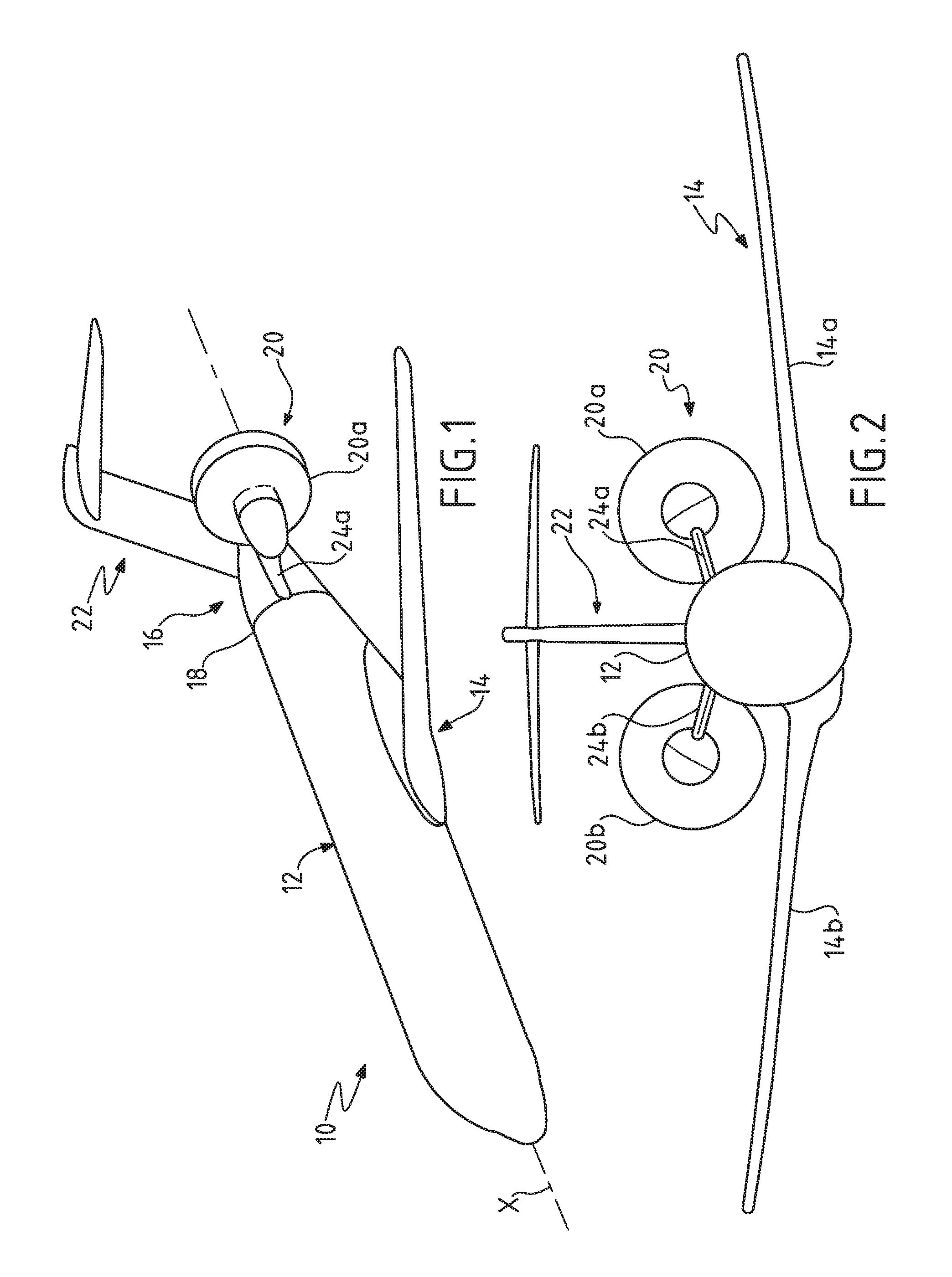
[0041]As shown in FIG. 1, only one half of an aircraft 10 according to the invention is shown. The other half, which is not shown, is obtained by symmetry with respect to the axial vertical plane which contains the longitudinal axis X of the aircraft.

[0042]The aircraft comprises a fuselage 12, a central airfoil 14 connected to the fuselage and a tail cone 16. The tail cone 16 comprises the rear part of the fuselage 18, an aft-mounted engine 20 connected to the rear part of the fuselage 18 and an empennage 22.

[0043]The aft-mounted engine in this case comprises, for example, an engine with contrarotating fans that is connected to the tail cone 16 by a pylon 24a fixed to the side of the tail cone shown in FIG. 1.

[0044]FIG. 2 shows the two wings 14a, 14b of the airfoil and the two engines 20a, 20b that are connected to the tail cone 16 by a respective pylon 24a, 24b.

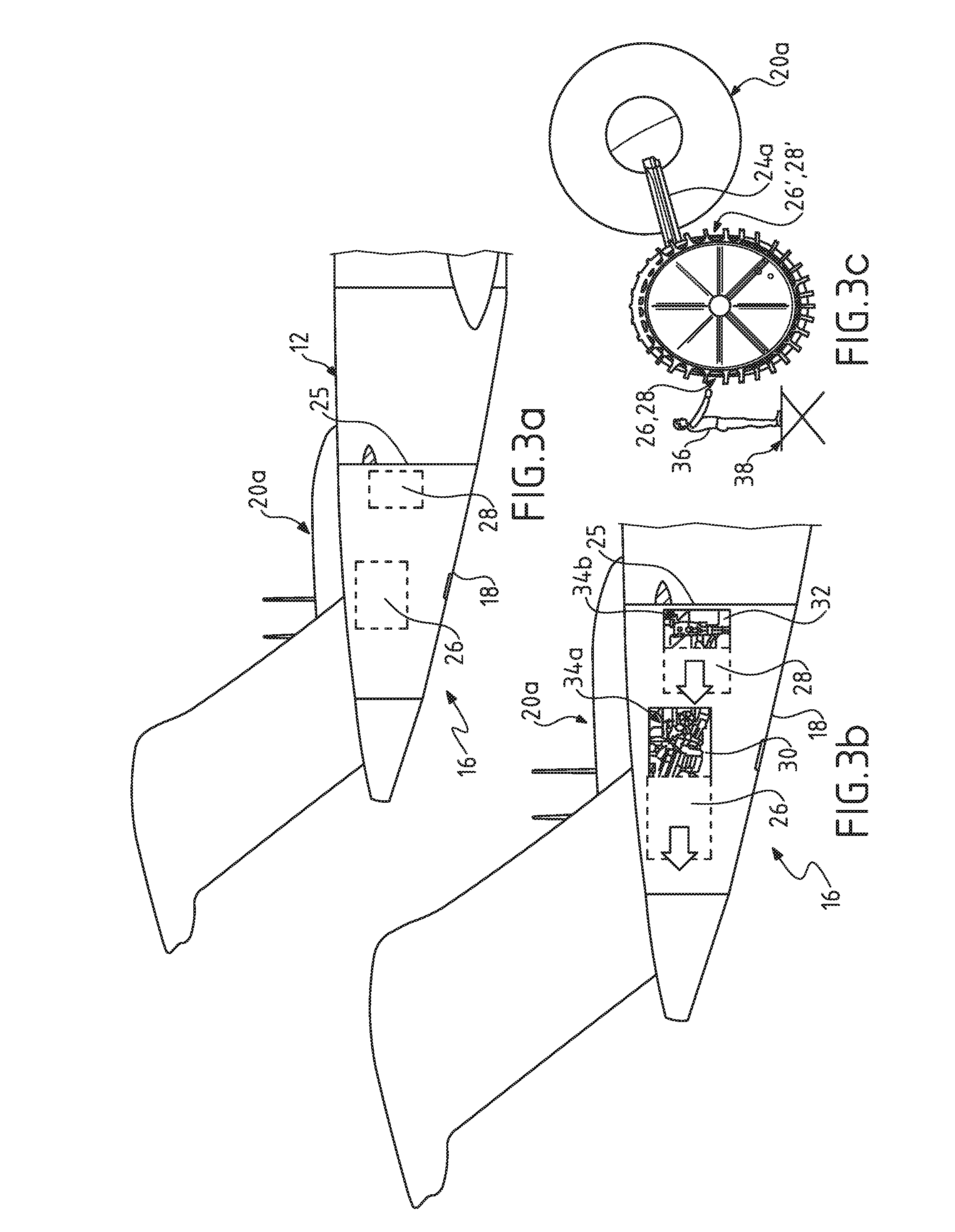
[0045]Only one of the two opposite sides of the fuselage is shown in FIGS. 3a-b, which illustrate the first embodiment in...

second embodiment

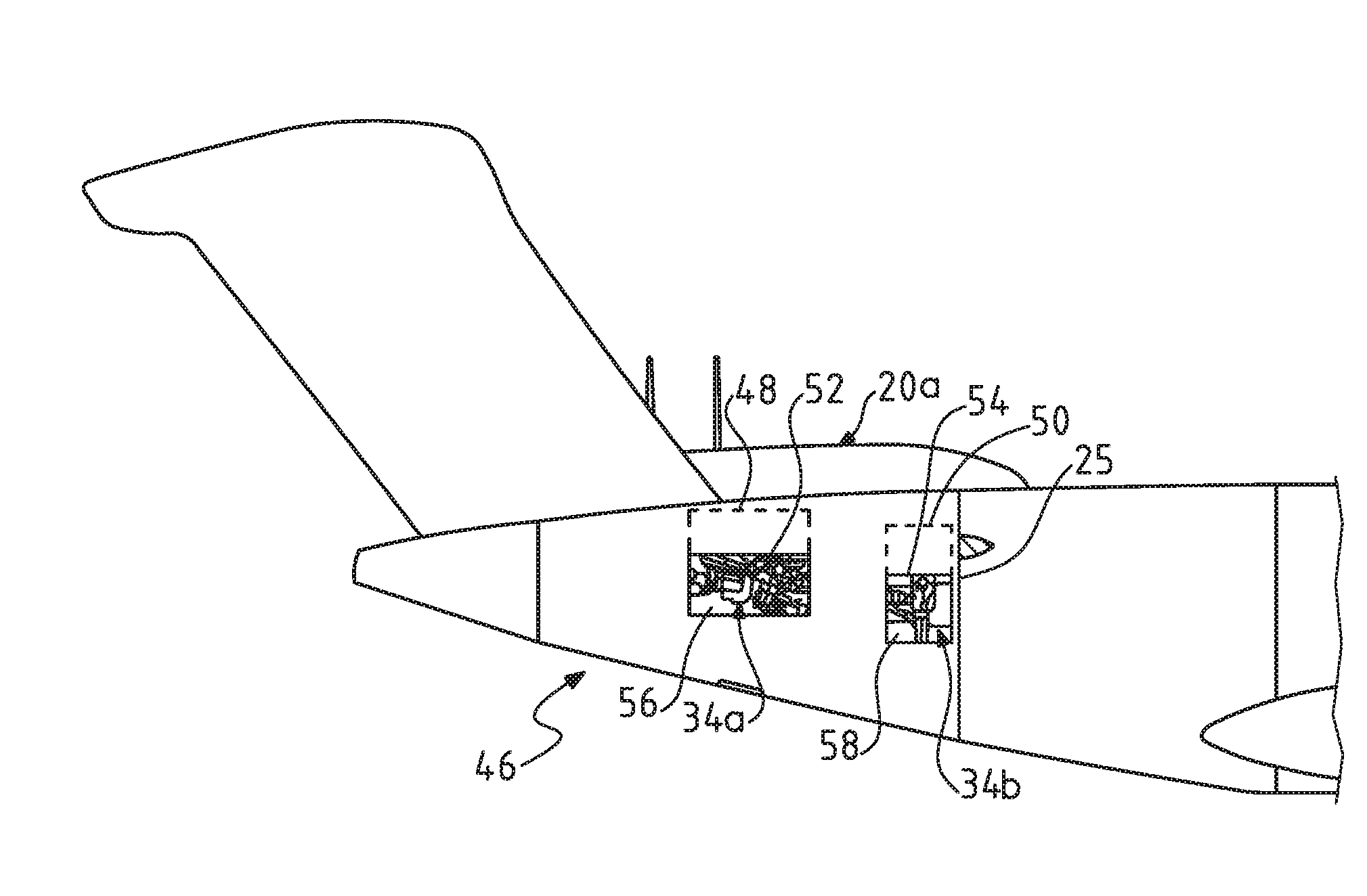
[0068]FIGS. 6a-b illustrate a tail cone 46 provided with two lateral hatches 48, 50 on each of the sides of the fuselage, as for the embodiment in FIGS. 3a-c. The shapes and dimensions of these hatches and the positions thereof are identical to those of the hatches in the embodiment in FIGS. 3a-c. The features described in relation to FIGS. 1, 2 and 4 apply to the embodiment in FIGS. 6a-b.

[0069]In this embodiment, the lateral hatches 48, 50 are each mounted in an articulated manner on the fuselage by way of a hinge system 52, 54 of the type used for the aircraft nacelle fairings.

[0070]The opening of the lateral hatches 48, 50 frees up respective corresponding lateral openings 56, 58, the features of which are identical to those in the embodiment in FIGS. 3a-c.

[0071]The lateral hatches 48, 50 mounted in an articulated manner are “non-acting”, i.e., they are not involved in the transmission of force to the fuselage. These hatches are used when the inspection and / or maintenance opera...


PUM


Abstract

An aircraft tail cone comprising a fuselage in which avionic equipment is housed. The tail cone comprises two lateral hatches formed in the fuselage, at least one hatch being formed on each of the two opposite sides of the fuselage. Each hatch is mounted removably with respect to the fuselage so as to take up a closed first position in which the hatch closes a lateral opening in the fuselage, and an open second position in which the open hatch allows access to the inside of the tail cone through the corresponding opening The avionic equipment that requires regular inspection and/or maintenance operations is housed in a part of the tail cone which is accessible through the two lateral openings in the fuselage to a person who remains on the outside of the fuselage.

Description

CROSS-REFERENCES TO RELATED APPLICATIONS[0001]This application claims the benefit of the French patent application No. 1551014 filed on Feb. 9, 2015, the entire disclosures of which are incorporated herein by way of reference.BACKGROUND OF THE INVENTION[0002]The invention relates to an aircraft tail cone.[0003]Most aircraft incorporate avionic equipment in their tail cone.[0004]This equipment comprises, for example, the systems for powering the control surfaces situated in the empennage, etc.[0005]In some aircraft, the engines are disposed at the tail cone of these aircraft.[0006]Thus, the tail cone incorporates equipment in addition to that listed above, namely, systems for powering the engines and auxiliary power units (APU), fuel (kerosene) circuits, hydraulic and electrical circuits, air circuits that supply the cabin with hot air which is taken from the engines and cooled, fire extinguishing systems and equipment (cylinders containing extinguishing agent), etc.[0007]In the type...

Claims


Application Information

Patent Timeline
Patent Type & Authority Applications(United States)
IPC IPC(8): B64C1/14B64C1/16B64C1/10
CPCB64C1/10B64C1/1446B64D27/20B64D27/14B64C1/16B64D29/08B64D37/005B64D2041/002Y02T50/40
Inventor SCHEEL, HENNINGBOUCHET, ERICGUILLEMAUT, JULIENMARTINO-GONZALEZ, ESTEBAN
Owner AIRBUS OPERATIONS (SAS)
Why Eureka
Try Eureka