
Light device, especially a headlight for motor vehicles

a technology for headlights and motor vehicles, applied in vehicle lighting systems, lighting and heating apparatuses, transportation and packaging, etc., can solve the problems of directing light beams from a higher number of led light sources, creating a suitable light pattern, and still remains a technical problem, and achieve the effect of increasing the difference in sharpness

Active Publication Date: 2016-08-11
PO LIGHTING CZECH SRO
View PDF7 Cites 11 Cited by
  • Summary
  • Abstract
  • Description
  • Claims
  • Application Information

AI Technical Summary

Benefits of technology

The patent describes a technical solution for improving the sharpness of cutting-edge equipment, such as lamps and lasers. The second diaphragm is designed to move in two directions, which increases the difference in sharpness between the borders created by this diaphragm and other borders. Additionally, a diaphragm is placed between each pair of output lenses to prevent the same rays of light from passing through both lenses. This reduces blurring and improves the overall quality of the equipment.

Problems solved by technology

However, LED light units individually have a low light output, which can be increased by using a high number of LED light sources, but directing light beams from a higher number of LED light sources and creating a suitable light pattern is difficult and thus it still remains a technical problem.
To create a sufficiently large dark unlit part in the place where the camera detects an oncoming vehicle, the LED light sources are switched off and on in sections in the shape of vertical stripes; however, their margins are diffused and no suitable technical means is provided to control the sharpness of the edges of the vertical stripes and to create a sharp light image.
A disadvantage of this design is the fact that the optical system poses high requirements for the installation space, while the light device with an exact position of individual diaphragms and collimating elements features a relatively long optical axis whose direction corresponds to that of the light axis of the vehicle x, which restricts variability of the mechanical design of the light device, e.g., the design of the arrangement of the cooling system.
Shortening of the optical axis results in a reduction of the focal distance of the optical elements, which enhances variability of the mechanical design, but the impact on the emission characteristics of the resulting light trace is negative.
A technical problem of these projection systems is creation of a compact display area with homogeneous light intensity all over the area, since at the contact edge of two neighbouring patterns or two light functions increased light intensity, or conversely, unlit places can be observed.
Another disadvantage is the fact that if a sharp transition between the lit and unlit part of the carriageway is created, the human eye concentrates on the lit part in such a way that it virtually does not see the unlit part.

Method used


Image

  • Light device, especially a headlight for motor vehicles
  • Light device, especially a headlight for motor vehicles
  • Light device, especially a headlight for motor vehicles

Examples


Embodiment Construction

OF EMBODIMENTS

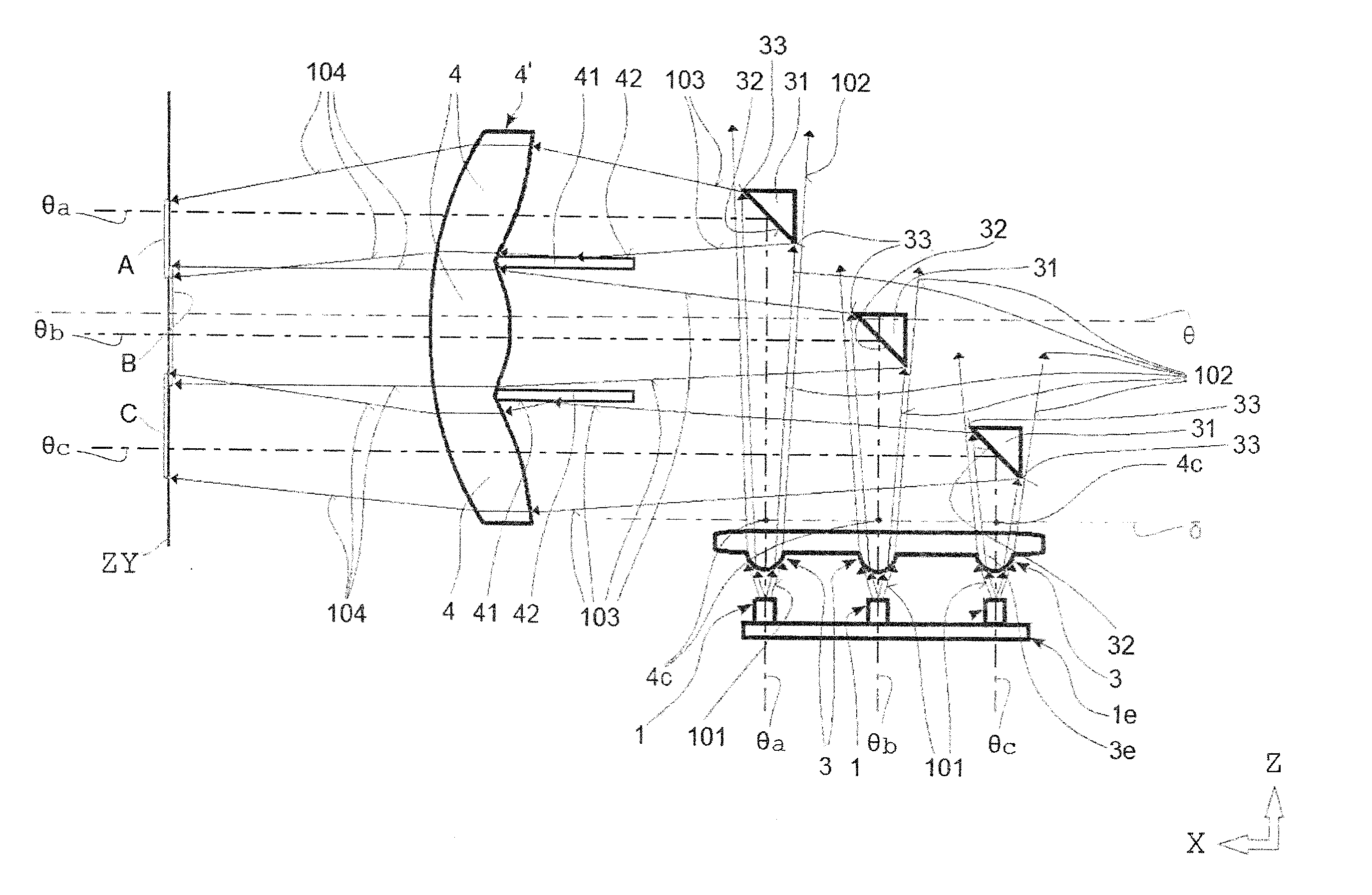
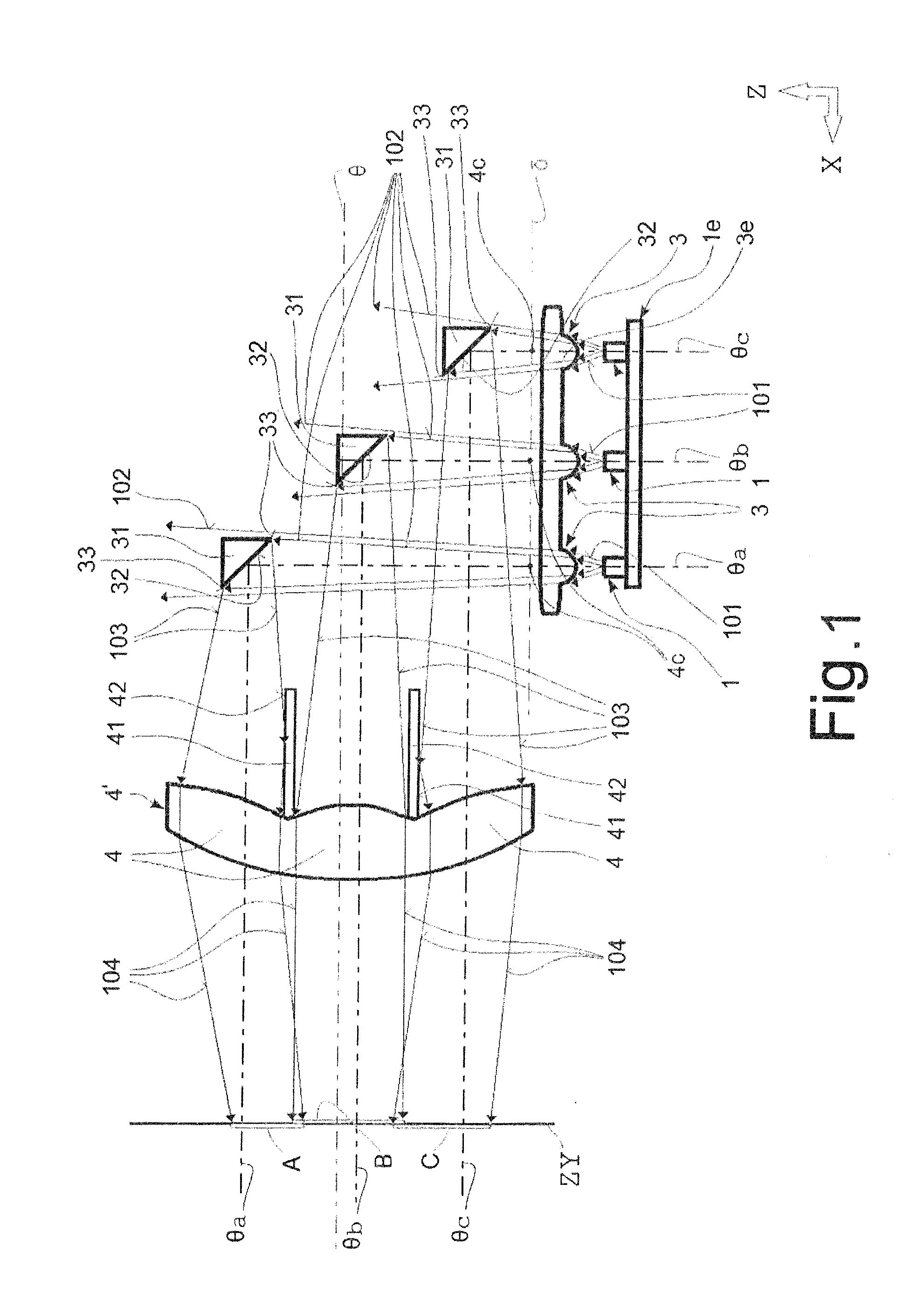
[0045]According to FIG. 1, which shows the first embodiment of the light device in accordance with the invention, the light device comprises a light source, consisting of a set or sets of light units 1, arranged on the carrier plate 1e, situated substantially in parallel (i.e. in parallel or approx. in parallel) to the optical axis θ of the light device and a diaphragm set containing reflective diaphragms 31 for creation of trim edges in the final light trace. On the light axes θa, θb, θc of the light units 1, in the transmission direction of the light rays 101, a collimating optical element 3 is arranged, containing collimating lenses 3e for concentration of the light rays 101 of the light units 1 to the direction of the light axes θa, θb, θc of the light units 1. The collimating optical element 3 is arranged in parallel to the optical axis θ of the light device. In the transmission direction of the light rays, after the collimating optical element 3 reflective diaphr...


PUM


Abstract

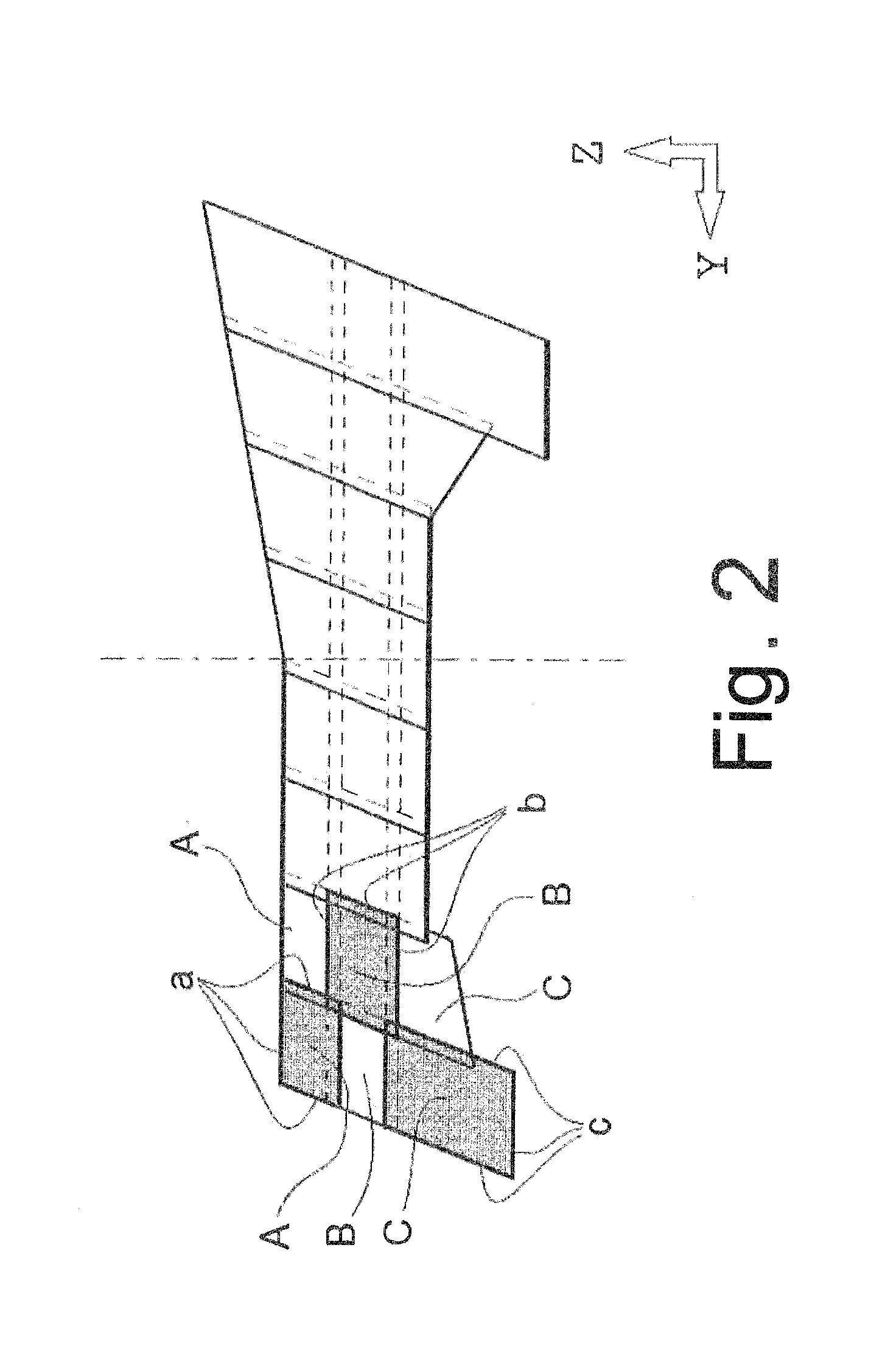
A light device, especially a headlight of motor vehicles, comprises at least one light unit (1), or a group (1a, 1b) of light units, at least one optical directing element (3, 2e, 3f), adapted to direct the light beam emitted by the light unit, or group of light units, to the required direction, and at least one output lens (4) for passage of at least a part of the light rays of the light beam or beams to create a light pattern (A, B, C) on the display surface (ZY). On the route of the light beam between the optical directing element and the output lens, there is at least one optical diaphragm element (11, 21, 31) containing a system of trim edges (13, 23, 33) to create the required shape of the cross-section of a part or parts of the light beam designed for transmission along the above-mentioned route.

Description

FIELD OF THE INVENTION[0001]The invention relates to a light device, especially an adaptive headlight for motor devices, and it relates to a light device containing a light-emitting optical system that contains controllable projection equipment to achieve the required emitting characteristic of the output light trace, while the light intensity can be variably changed in specific zones of the light trace.BACKGROUND INFORMATION[0002]A headlight, especially for motor vehicles, contains at least one optical system comprising a powerful light source and optical elements. The light source emits light rays and the optical elements represent a system of refractive and reflective surfaces, interfaces of optical environments and diaphragms that influence the direction of light rays within the creation of the output light trace.[0003]In modern headlights of motor vehicles, light sources consisting of LED light units are frequently used. An advantage of the LED light units is their long service...

Claims


Application Information

Patent Timeline
Patent Type & Authority Applications(United States)
IPC IPC(8): F21S8/10F21S41/147F21S41/148F21S41/151F21S41/24F21S41/25F21S41/265
CPCF21S48/125F21S48/145F21S48/1159F21S48/1241F21S41/285F21S41/24F21S41/265F21S41/321F21S41/43F21S41/25F21S41/148F21S41/151F21S41/26F21S45/43F21S45/49B60Q1/06
Inventor KRATOCHVIL, JANPEKARKOVA, DANAHASA, ONDREJGROF, JANMACICEK, MILOSMIKESKA, ZDENEKKYTKA, MILANORLITA, RADEKDAVID, TOMASHYNAR, DAVID
Owner PO LIGHTING CZECH SRO
Learn More