Zoom spotlight

a spotlight and zoom technology, applied in the field of spotlights, can solve problems such as compromising the efficiency of us

Inactive Publication Date: 2016-08-11
JRF PHOTONICS TECH CO LTD
View PDF5 Cites 7 Cited by
  • Summary
  • Abstract
  • Description
  • Claims
  • Application Information

AI Technical Summary

Benefits of technology

The present invention has the advantage of being easy to manufacture and low-cost. It can produce a wide beam, a collimated beam, or a beam that falls between the two.

Problems solved by technology

On the other hand, most of the conventional spotlights require a complicated manufacturing process in mass production, and the finished spotlights are simply incapable of outputting an approximately collimated beam, meaning stray light will be generated during operation and thus compromise efficiency of use.

Method used


Image

  • Zoom spotlight
  • Zoom spotlight
  • Zoom spotlight

Examples


Embodiment Construction

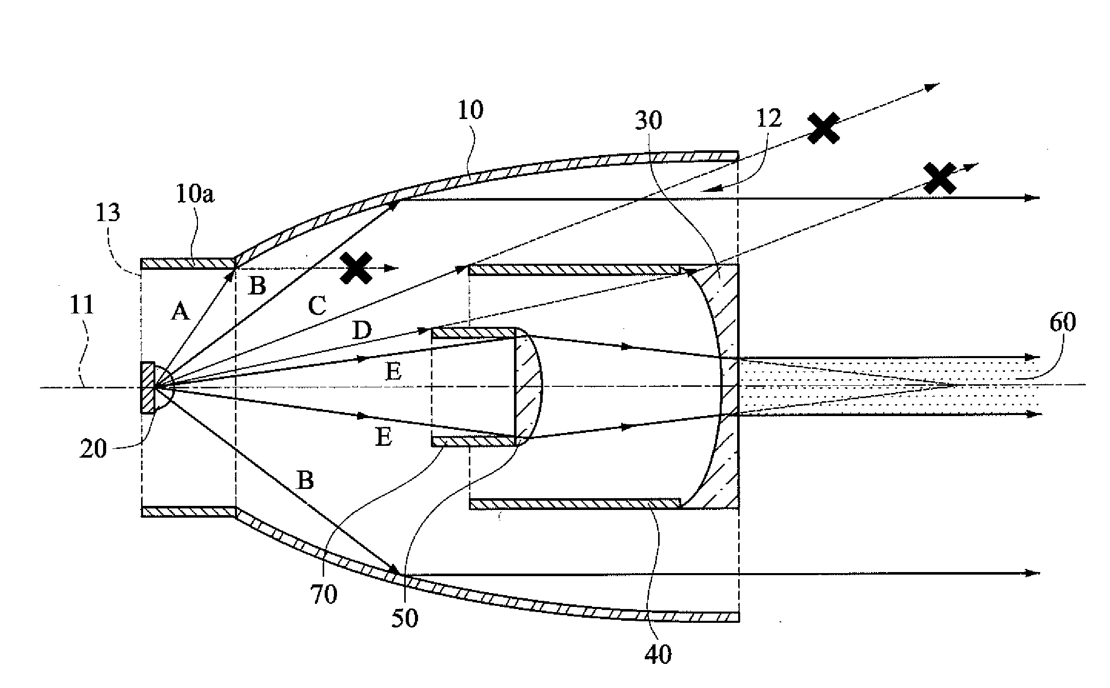
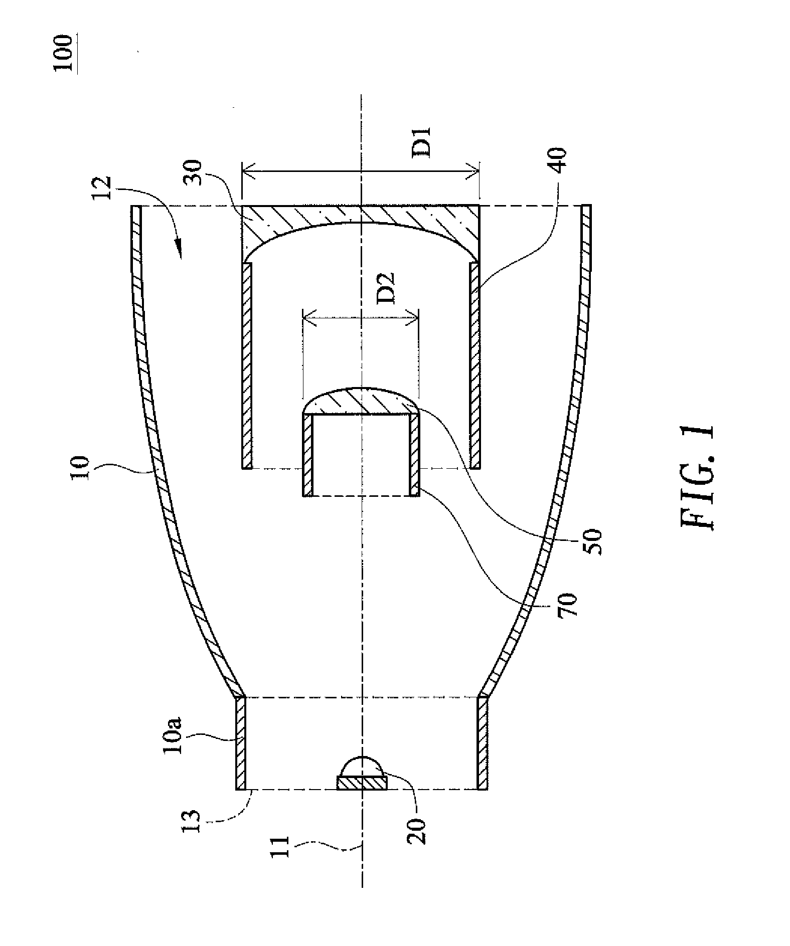
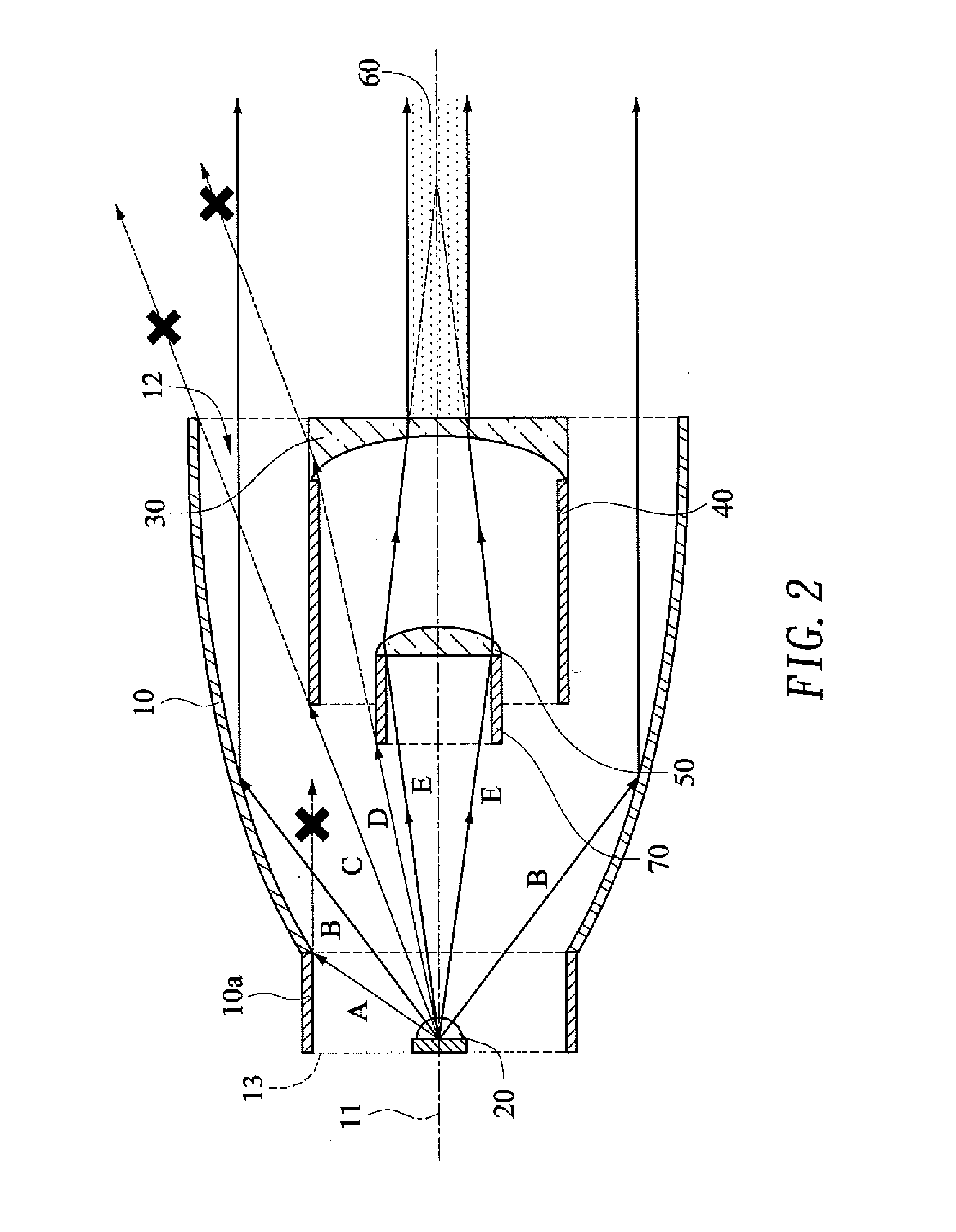
[0023]Referring to FIG. 1, the zoom spotlight 100 in an embodiment of the present invention includes a reflector 10, a light source 20, a fixed lens 30, and a movable lens 50.

[0024]As shown in FIG. 1, the reflector 10 has a central axis 11, a light exit opening 12, and a bottom side 13 opposite the light exit opening 12. The central axis 11 is the line connecting the center point of the light exit opening 12 and the center point of the bottom side 13. The shape or material of the reflector 10 is such that the inner surface of the reflector 10 can reflect incident light and project the reflected light out of the light exit opening 12 by method of approximate collimating beam or small divergence angle.

[0025]With continued reference to FIG. 1, the light source 20 is fixedly provided at the bottom side 13, located on the central axis 11, and opposite the light exit opening 12. The light source 20 can be at least one LED, at least one OLED, or a combination of at least one LED and at lea...


PUM


Abstract

A zoom spotlight has a reflector, a light source, a fixed lens, and a movable lens. The movable lens of the zoom spotlight can be moved and thereby adjusted in position relative to the fixed lens so that the zoom spotlight can output a broad beam, a collimated beam, or a beam ranging between the broad beam and the collimated beam, according to the user's needs.

Description

BACKGROUND OF THE INVENTION[0001]1. Technical Field[0002]The present invention relates to a spotlight and more particularly to a zoom spotlight with a fixed lens and a movable lens.[0003]2. Description of Related Art[0004]The market demand for energy-saving products is increasing with the modernization of society and the rise of environmental awareness. Meanwhile, rapid development of the light-emitting diode (LED) and organic light-emitting diode (OLED) industry has lowered the costs of LEDs and OLEDs significantly, turning these lighting elements into the mainstream of energy-saving illumination.[0005]In particular, LEDs and OLEDs are widely used in spotlights, especially high-power LED spotlights, which are nowadays the principal products in spotlight applications. The conventional spotlights, which feature high power consumption and tend to generate heat easily, have given way to high-power LED spotlights in such fields as special lighting, search and rescue, stage and runway de...

Claims


Application Information

Patent Timeline
IPC IPC(8): F21V5/04F21V29/70F21V5/00F21V13/04
CPCF21V5/04F21V13/04F21Y2101/02F21V5/008F21V29/70F21V5/048F21V11/16F21V13/02F21V13/12F21V14/06F21Y2115/10F21Y2115/15
Inventor WANG, CHIU-FENLEE, XUAN-HAOLIN, CHE-CHU
Owner JRF PHOTONICS TECH CO LTD
Why Eureka
Try Eureka