
Mobile body

a mobile body and body technology, applied in the field of mobile bodies, can solve the problems of annular route problems on partial maps, difficult automatic creation of maps, etc., and achieve the effect of speeding up the restoration of environmental maps

Inactive Publication Date: 2016-08-11
MURATA MASCH LTD
View PDF0 Cites 6 Cited by
  • Summary
  • Abstract
  • Description
  • Claims
  • Application Information

AI Technical Summary

Benefits of technology

The patent describes a mobile body that creates an environmental map based on position information about obstacles. The mobile body can determine which parts of the map should be deleted and which parts should be included. By doing this, the created map is less likely to have issues with accurately navigating through obstacles. The mobile body can also estimate the future position of the obstacles and prevent them from being deleted from the map. This helps to improve the accuracy and efficiency of creating the environmental map.

Problems solved by technology

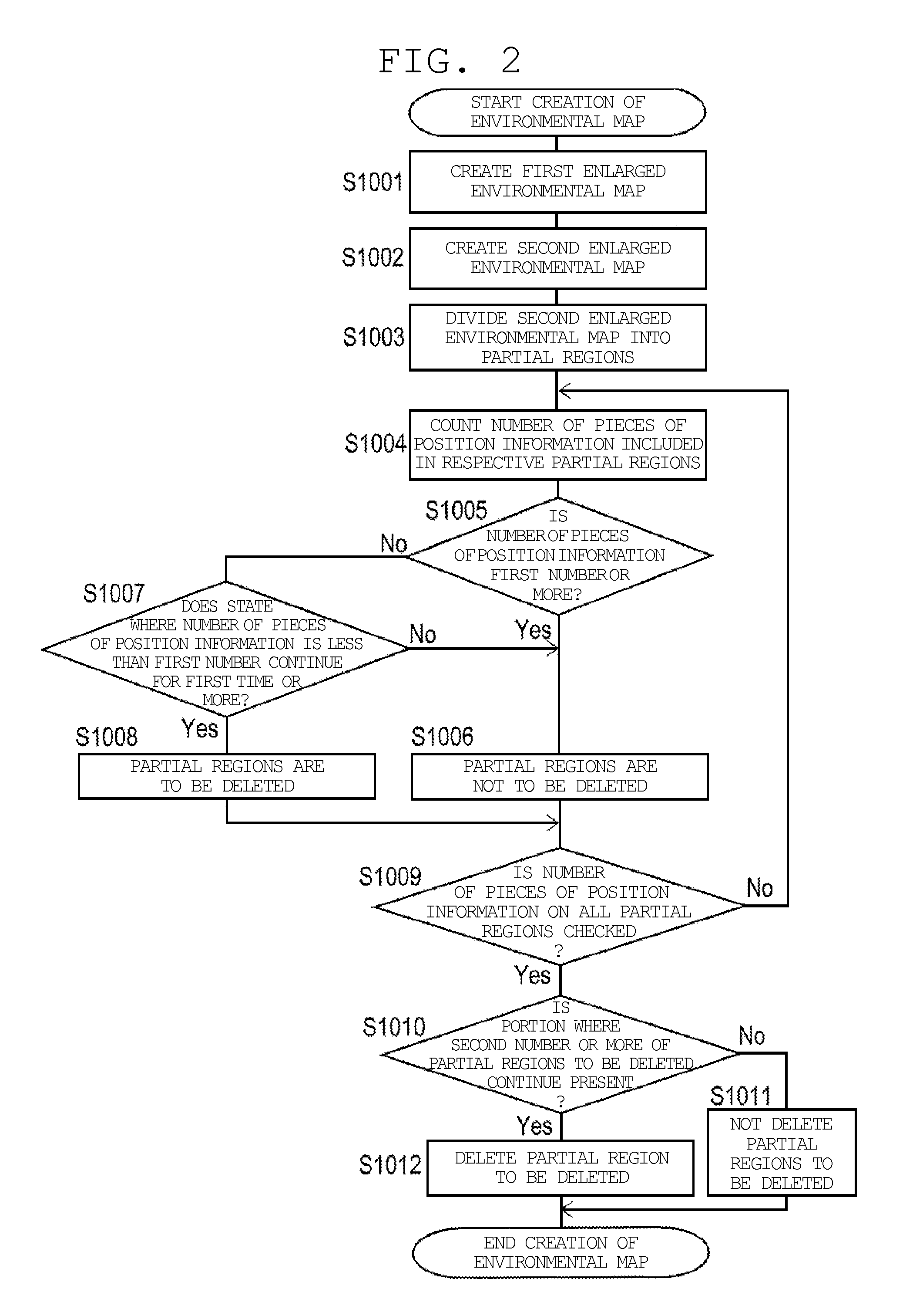
In the method for creating the environmental map according to the SLAM, when a circular environmental map is created, a start portion and an end portion occasionally do not match with each other (a so-called annular route problem) because measurement errors are accumulated.
In this case, it is difficult to plan creation of the partial maps considering how the environment map is divided, and thus automation of the creation of the map is difficult.
Further, particularly when a laser range finder or a camera in which measurable distance is large is used and a region where a mobile body moves is equivalent or narrower than a region whose distance can be measured by the laser range finder or the camera, the annular route problem arises on the partial maps even when the environmental map is divided into the plurality of partial maps.

Method used


Image

  • Mobile body
  • Mobile body
  • Mobile body

Examples


first preferred embodiment

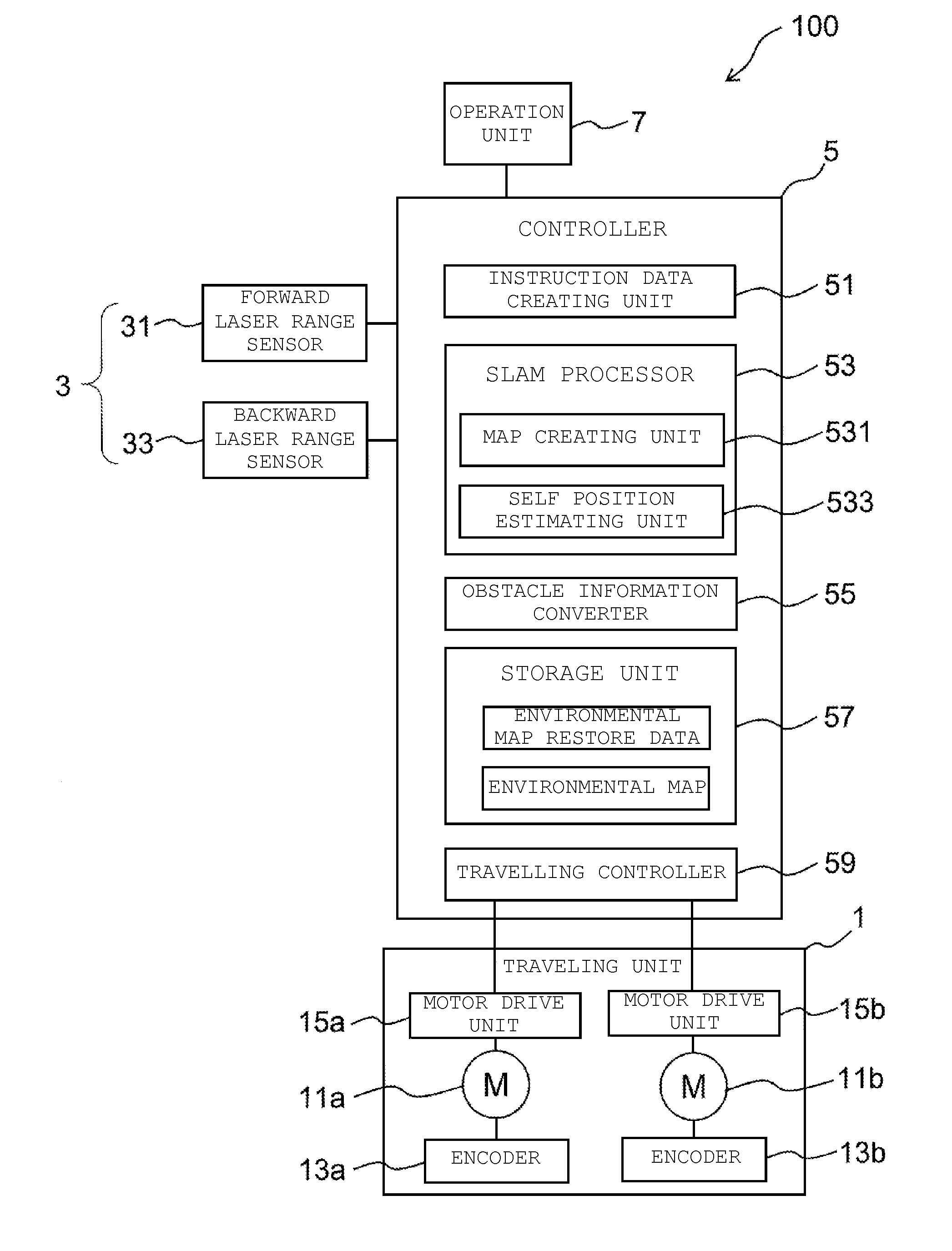
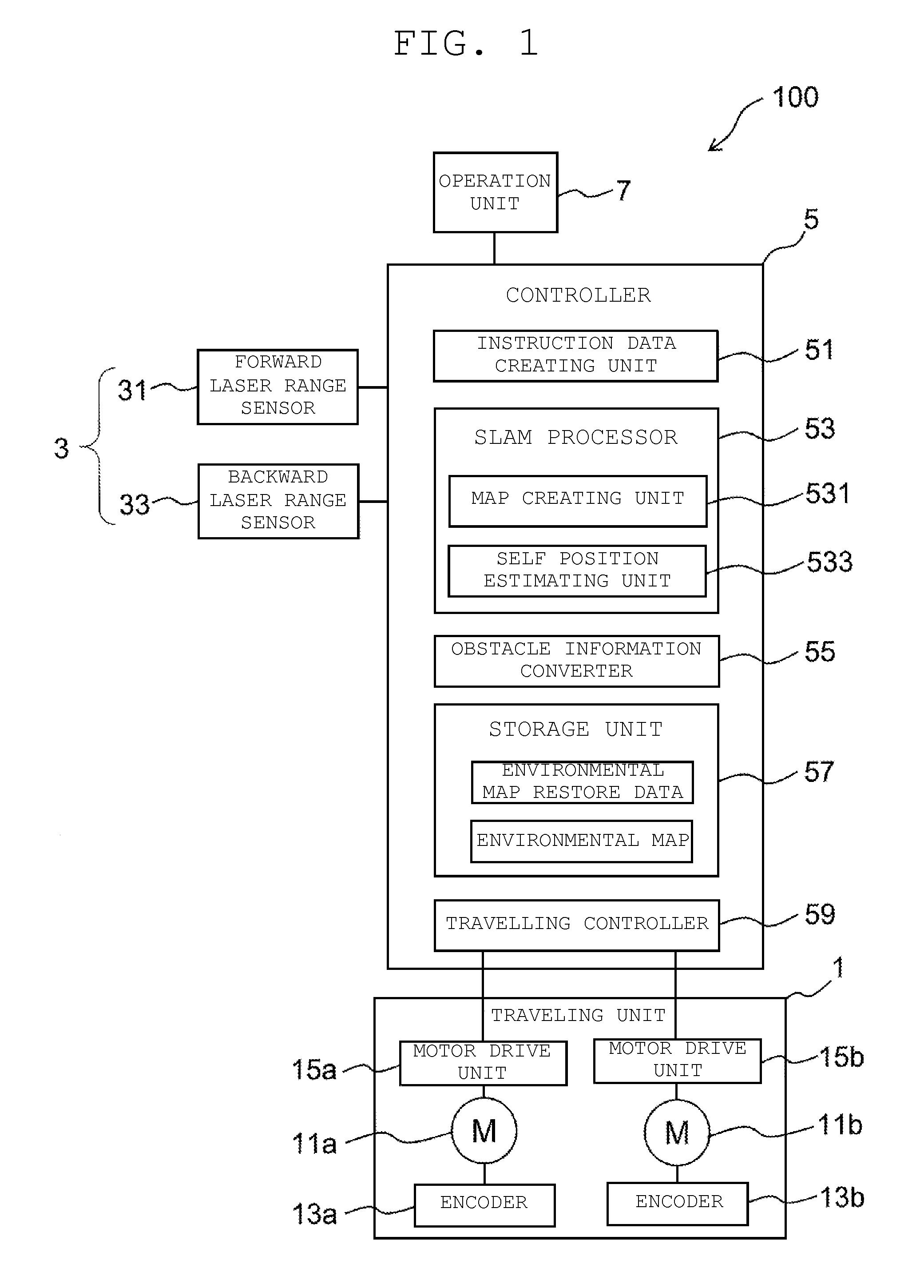
[0053]An entire configuration of a mobile body 100 according to a first preferred embodiment of the present invention is described below with reference to FIG. 1.

[0054]The mobile body 100 preferably includes a traveling unit 1, an obstacle information obtaining unit 3, and a controller 5. The traveling unit 1 is provided to a main body of the mobile body 100, and moves the mobile body 100 in a predetermined moving region.

[0055]The obstacle information obtaining unit 3 includes a forward laser range sensor 31 provided to a front side of the mobile body 100 in a traveling direction, and a backward laser range sensor 33 provided to a rear side of the mobile body 100 in the traveling direction. The sensors 31 and 33 detect obstacles on front and rear sides of the mobile body 100.

[0056]The forward laser range sensor 31 and the backward laser range sensor 33 are Laser Range Finders (LRF) that emit laser beams pulse-oscillated by laser oscillators to target objects such as obstacles, respe...


PUM


Abstract

A mobile body includes an obstacle information obtaining unit, a storage unit, a self-position estimating unit, and a map creating unit. The obstacle information obtaining unit obtains position information about an obstacle. The storage unit stores environmental map restore data and an environmental map created at a previous time. The self-position estimating unit estimates an estimated position based on a comparison between the environmental map created at a previous time and the position information about the obstacle obtained by the obstacle information obtaining unit. The map creating unit creates an enlarged environmental map, and deletes, out of regions included in the enlarged environmental map, a region corresponding to a non-information region from the enlarged environmental map, so as to create an environmental map on an estimated position.

Description

CROSS-REFERENCE TO RELATED APPLICATIONS[0001]This application claims priority under 35 U.S.C. 119 to Japanese Patent Application No. 2014-221200, filed on Oct. 30, 2014, which application is hereby incorporated by reference in its entirety.BACKGROUND OF THE INVENTION[0002]1. Field of the Invention[0003]The present invention relates to a mobile body that travels in a moving region while estimating a position in the moving region.[0004]2. Description of the Related Art[0005]Conventionally, a mobile body that autonomously moves in an ambient environment is known. When the mobile body autonomously moves in an ambient environment, an environmental map illustrating regions in a moving space where an object (hereinafter, an obstacle) is present and is not present is necessary. As a method for obtaining such an environmental map, various methods have been invented, but in recent years, attention has been paid to SLAM (Simultaneous Localization and Mapping) as a technique for estimating posi...

Claims


Application Information

Patent Timeline
Patent Type & Authority Applications(United States)
IPC IPC(8): G05D1/00
CPCG05D1/0088G05D1/024G05D1/0274
Inventor KANAME, HIDEKINAKANO, TSUYOSHI
Owner MURATA MASCH LTD
Learn More