Electronic image processing device and system for image data transfer operation

Inactive Publication Date: 2008-06-10
NIKON CORP
View PDF13 Cites 19 Cited by
  • Summary
  • Abstract
  • Description
  • Claims
  • Application Information

AI Technical Summary

Benefits of technology

[0009]An object of the present invention is to provide an electronic device and an electronic system capable of performing different processing depending upon whether or not image data are to be transferred so that, for instance, image data to be transferred are prevented from being deleted by mistake.

Problems solved by technology

In addition, since a recording medium mounted at an electronic camera has a limited recording capacity, unnecessary image data, i.e., image data with no transfer marking attached thereto, are normally erased from the recording medium to allow image data obtained through a subsequent photographing operation to be recorded into the recording medium.
However, there is a possibility of the image data with the transfer marking attached thereto, i.e., the image data that the user wishes to save, being erased by mistake while erasing unnecessary image data in the electronic camera in the related art.

Method used


Image

  • Electronic image processing device and system for image data transfer operation
  • Electronic image processing device and system for image data transfer operation
  • Electronic image processing device and system for image data transfer operation

Examples


first embodiment

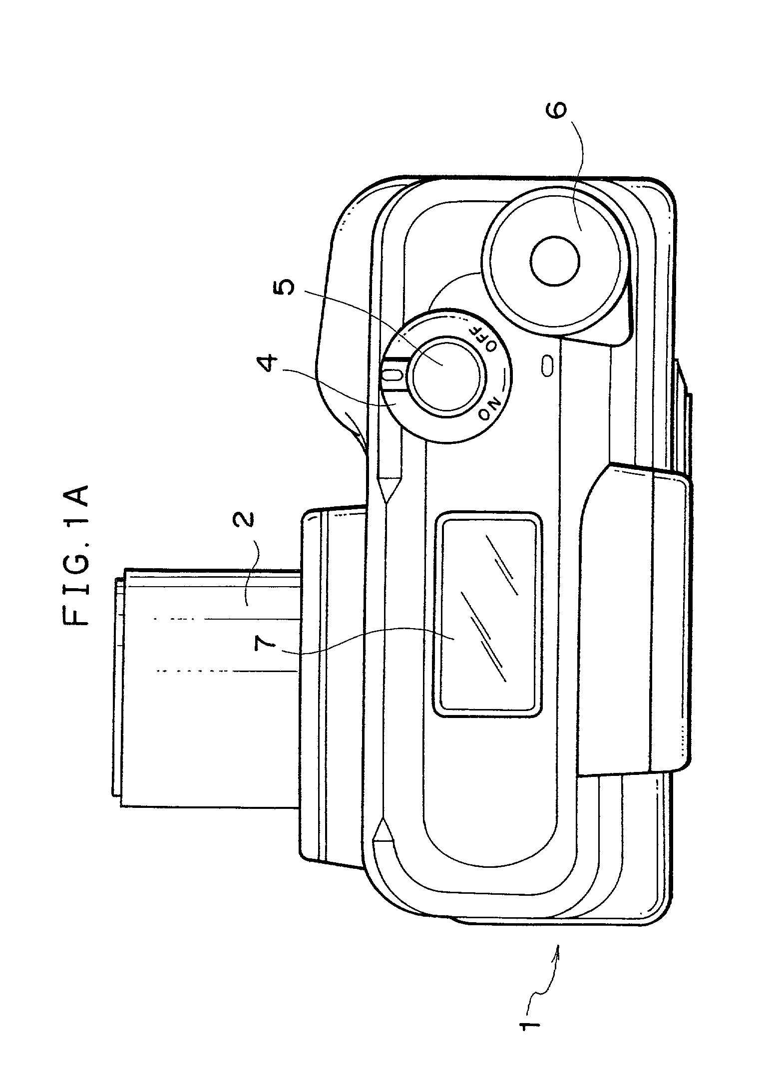
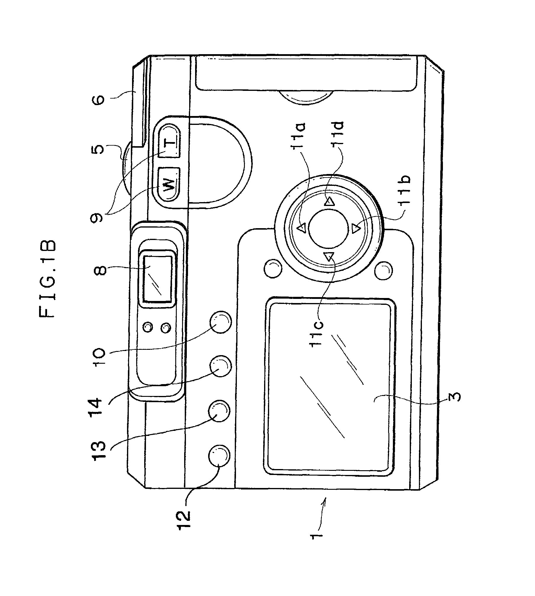
[0043]The following is an explanation of the first embodiment of the electronic device and the electronic system according to the present invention, given in reference to the drawings. FIGS. 1A and 1B illustrate the electronic device achieved in the first embodiment. FIG. 1A is a plan view of an electronic camera 1 and FIG. 1B is a rear view of the electronic camera 1. As shown in FIG. 1A, at the upper surface of the electronic camera 1, a main switch 4 through which the power is turned on / off, a shutter release button 5 through which a photographing operation is executed and a display panel 7 at which camera information is displayed are provided.

[0044]The electronic camera 1 assumes a recording mode in which image data obtained by photographing a subject are recorded into a memory card 424 to be detailed later and a reproduction mode in which the image data recorded in the memory card 424 are read out and the image data thus read out are reproduced and displayed at a display LCD 3 ...

second embodiment

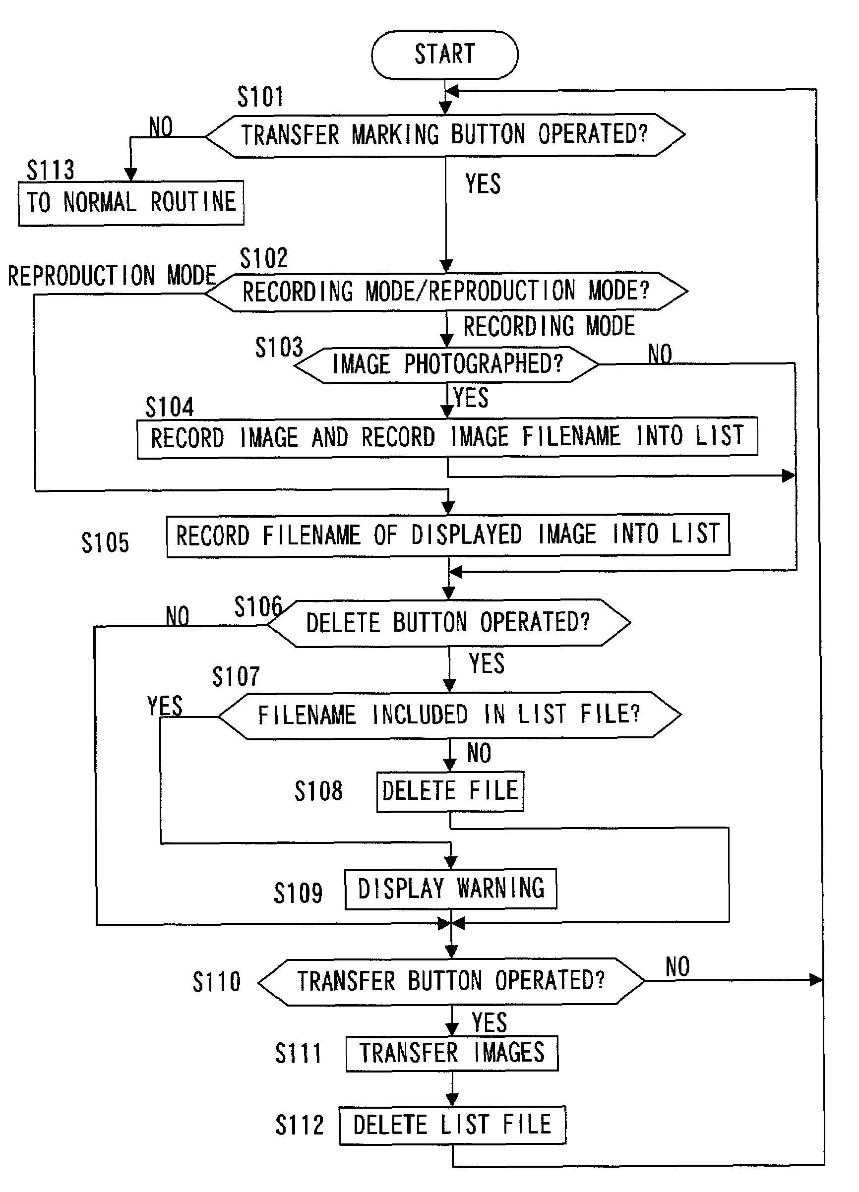
[0099]While the transfer marking is set by recording a filename 49 in the list file 47 in the first embodiment, tag information related to transfer marking is recorded in an image file 45 as additional information in the second embodiment. It is to be noted that the term “tag information” in this context refers to information that can be made to correlate to the image data contained in the image file 45. The PC 20 judges as to whether or not each image file 45 is appended with tag information and reads only image files 45 appended with the tag information into the PC 20.

[0100]FIG. 12 presents a flowchart similar to the flowchart in FIG. 8, showing the procedure of the processing starting with appending the transfer marking and ending with completing the image transfer. The same step numbers are assigned to steps in which processing identical to that in the flowchart in FIG. 8 is performed. The following explanation focuses on the procedure of processing that is different from that i...

third embodiment

[0110]FIG. 13 is a rear view of an electronic camera 1 achieved in the third embodiment. The plan view of the electronic camera 1 is identical to the plan view of the first embodiment presented in FIG. 1A. The transfer button 12 in the electronic camera in the third embodiment achieves both a transfer function and a marking function. When the USB communication cable 21 (see FIG. 15) is connected to the USB connector terminal 23, the transfer marking button 12A functions as a transfer button, and it functions as a marking button once the USB cable 21 is disengaged. An external power connector terminal15 is provided to allow an AC adapter (not shown) to be connected. A detection device 457 (see FIG. 14) detects whether or not the AC adapter is currently connected to the external power connector terminal 15. The USB connector terminal 23 and the external power connector terminal 15 are provided inside a cover 16. As the cover 16 is opened, the terminals 23 and 15 become exposed.

[0111]F...


PUM


Abstract

An electronic device comprises an image-capturing device that captures an image of a subject, a recording device that records image files of images captured by the image-capturing device into a recording medium, a specifying information forming device that forms image specifying information for specifying an image file in the recording medium separately from the image files, a communication device that transfers image files recorded in the recording medium to an external recording device, a transfer instruction operation unit that issues an instruction for the communication device to transfer the image file specified in the image specifying information and a processing device that processes the image files differently depending upon whether or not image specifying information has been formed in the recording medium with respect to the recorded image files.

Description

INCORPORATION BY REFERENCE[0001]The disclosures of the following priority applications are herein incorporated by reference:[0002]Japanese Patent Application No. 2001-126497 filed Apr. 24, 2001[0003]Japanese Patent Application No. 2001-126500 filed Apr. 24, 2001BACKGROUND OF THE INVENTION[0004]1. Field of the Invention[0005]The present invention relates to an electronic device and an electronic system that includes an electronic device.[0006]2. Description of the Related Art[0007]In an electronic camera such as a digital still camera, data of a photographed image are recorded in a memory internally provided in the camera or in a recording medium such as a memory card mounted at the camera. Following the photographing operation, the image data may be transferred to a recording device such as a personal computer or the like via a communication cable. There is a technology in the related art that allows specific images to be saved for later use by attaching a transfer marking to the im...

Claims


Application Information

Patent Timeline
Patent Type & Authority Patents(United States)
IPC IPC(8): H04N5/76H04N5/765H04N5/77H04N5/907
CPCH04N5/772H04N5/765H04N5/907
Inventor KOBAYASHI, TOSHIAKIEJIMA, SATOSHI
Owner NIKON CORP
Why Eureka
Try Eureka