
Bone Conduction Hearing Aid System

a hearing aid and bone conduction technology, applied in the field of hearing aid systems, can solve the problems of headaches and skin irritation, constant pressure on the skull bone, and inability to use, and achieve the effect of efficient manufacturing

Active Publication Date: 2016-08-11
MED EL ELEKTROMEDIZINISCHE GERAETE GMBH
View PDF5 Cites 44 Cited by
  • Summary
  • Abstract
  • Description
  • Claims
  • Application Information

AI Technical Summary

Benefits of technology

This patent is about a bone conduction hearing device with a rotatable housing and interface connector. The device can be adjusted to change its orientation on the user's head without needing to tear off the skin interface or attach a new one. The device has a skin adhesive for comfortable connection to the user's skin and a cushioning layer to ensure a comfortable fit. The device is also designed to be connected to the user's bones through bone conduction, allowing for effective sound transmission. The patent also describes a method for manufacturing the skin adhesive and replacing it when needed. The technical effects of the invention include improved flexibility and comfort for users and efficient manufacturing.

Problems solved by technology

For the traditional bone conductors with a spring arrangement around the head, the constant pressure against the skull bone often causes headaches and skin irritation.
The spring arrangement is also bulky and is not a practical or user friendly solution.
This type of bone conductor may be designed with a permanent skin penetration which may lead to problems with skin infections.
If this type of bone conductor is instead designed with an implanted vibrator and where energy are transmitted from an external hearing aid there is a significant energy loss when transmitting the energy with an inductive link through the skin.
Another drawback is that the vibrator cannot easily be repaired if it breaks down.
For this type of bone conductor, surgery is still required and the magnetic force may cause skin necrosis due to the constant pressure against the skin and the hearing aid may also easily fall off.

Method used


Image

  • Bone Conduction Hearing Aid System
  • Bone Conduction Hearing Aid System
  • Bone Conduction Hearing Aid System

Examples


Embodiment Construction

[0039]In the past, it has been assumed that it is necessary to apply a fairly large pressure to transmit bone conduction vibrations through the skin regardless of whether the bone conductor has been applied with an elastic or adhesive arrangement. In embodiment of the present invention, it has been surprisingly realized that bone conduction can work efficiently without any significant pressure being applied against the skin.

[0040]In prior art hearing aid systems, it was assumed that an adhesively attached bone conductor required an adhesive patch that extended over the hearing aid device so that the ends of the adhesive patch can be attached to the head. The prior art adhesive patch or band encloses the hearing aid device, and the adhesive is therefore attached directly to the top of the hearing aid device to hold the entire hearing aid system in place on the head of the user. But by stretching the adhesive patch over the hearing aid device, the adhesive patch also provides an inwar...


PUM


Abstract

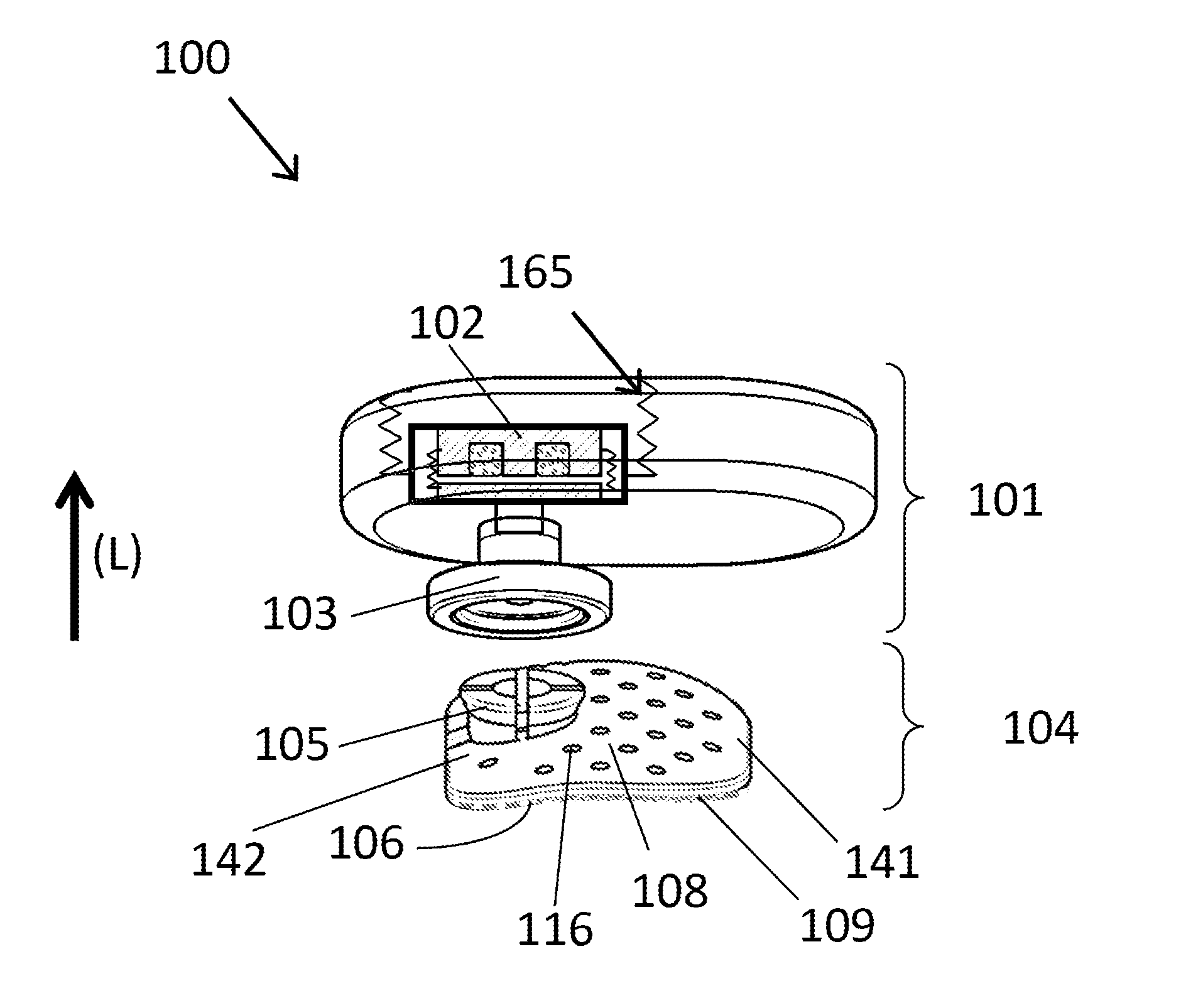
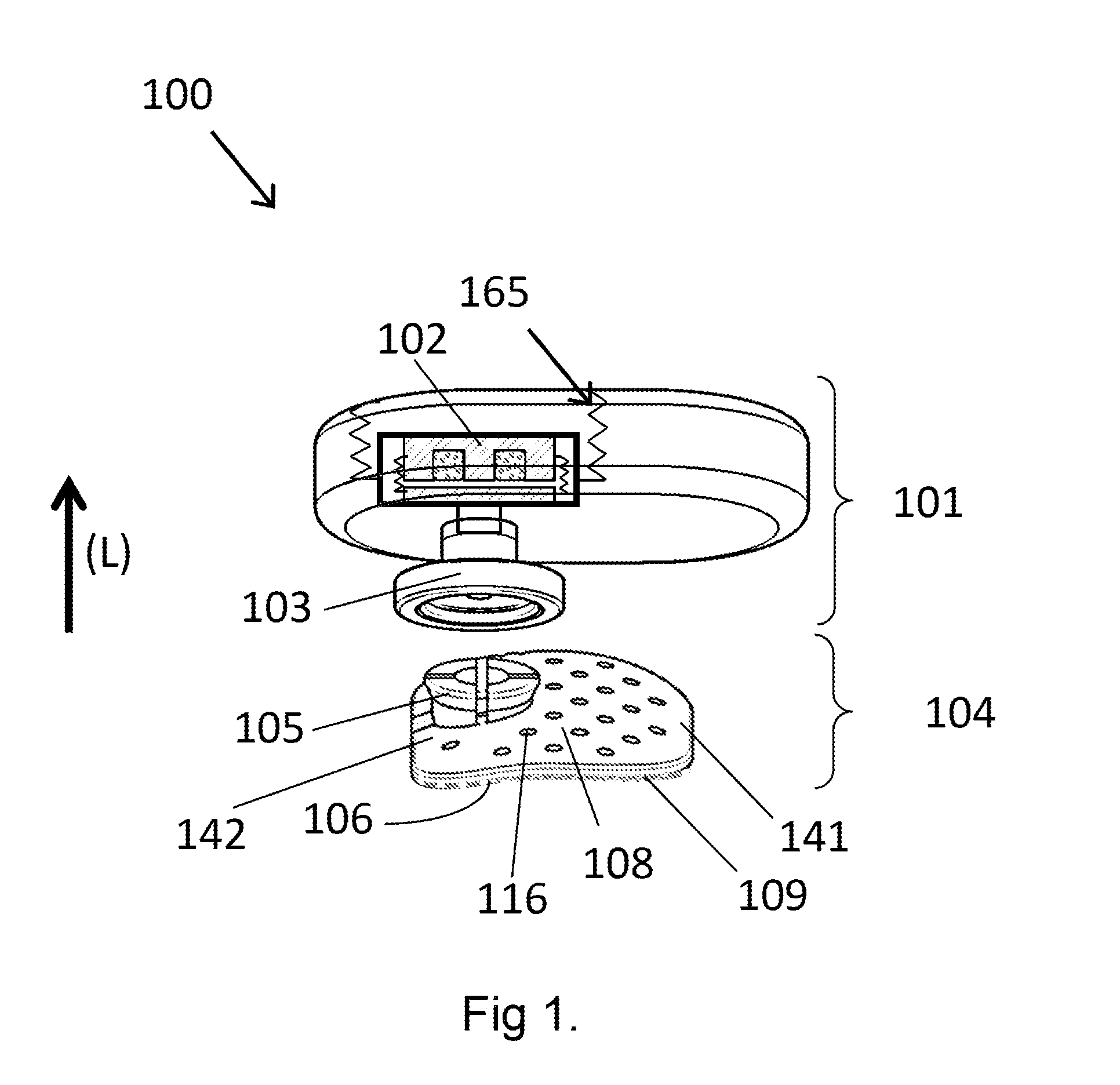
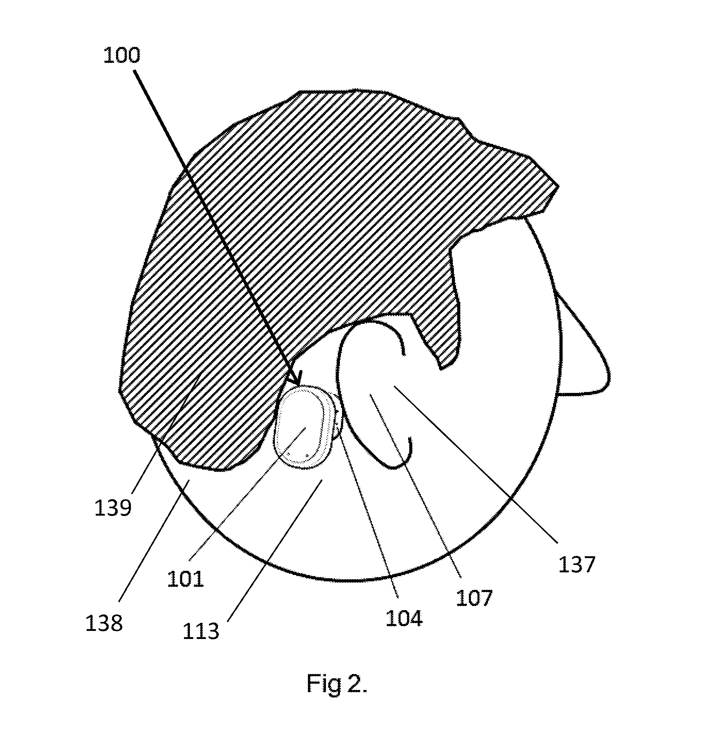
A bone conduction hearing aid system includes a hearing aid housing with a hearing aid vibrator. A skin interface has an interface connector offset on an outer interface surface and detachably connected to a housing connector. A skin adhesive connects to the skin of a patient user to transmit the sound vibrations through the skin to underlying skull bone for transmission by bone conduction to a hearing organ of the user. When the skin adhesive is pressed against the skin of the user, the skin is initially engaged during an initial engagement period with an initial adhesive force that promotes removal and relocation of the skin interface, and the skin is fully engaged after the initial engagement period with a full adhesive force greater than the initial adhesive force that promotes a fixed secure connection that resists removal of the skin interface.

Description

[0001]This application is a continuation-in-part of pending Patent Cooperation Treaty Application PCT / US2014 / 046146, filed Jul. 10, 2014, which in turn claims priority from U.S. patent application Ser. No. 13 / 963,186, filed Aug. 9, 2013, both of which are incorporated herein by reference in their entireties.FIELD OF THE INVENTION[0002]The present invention relates to a hearing aid system providing bone conduction hearing.BACKGROUND ART[0003]Bone conduction is the conduction of sound to the inner ear through the bones of the skull, and a bone conduction hearing aid, or bone conductor, is a device that stimulates through bone conduction. Other types of hearing aids may instead directly stimulate the tympanic membrane, the middle ear ossicles, the round window, the oval window or the cochlear fluid. Several different types of bone conduction hearing aids are available. A bone conduction hearing aid may amplify sound or it may also work as a tinnitus masker. A bone conductor may also be...

Claims


Application Information

Patent Timeline
IPC IPC(8): H04R25/00
CPCH04R25/606H04R2225/67H04R25/60H04R2460/13H04R25/75
Inventor WESTERKULL, PATRIK
Owner MED EL ELEKTROMEDIZINISCHE GERAETE GMBH
Learn More