Endoscope apparatus

a technology of endoscope and endoscope, which is applied in the field of endoscope equipment, can solve the problems of large amount of heat generation and large elements

Active Publication Date: 2016-08-18
OLYMPUS CORP
View PDF27 Cites 11 Cited by
  • Summary
  • Abstract
  • Description
  • Claims
  • Application Information

AI Technical Summary

Benefits of technology

[0009]An endoscope apparatus according to one aspect of the present invention includes: a first light source portion configured to generate light; a second light source portion configured to generate light; first cooling means configured to cool the first light source portion; second cooling means configured to cool the second light source portion; a light guiding portion configured to be inserted into a subject and configured to be capable of guiding the light from the first light source portion and the light from the second light source portion and capable of emitting the guided light from a distal end; an image pickup portion configured to receive light from the subject to which the lights emitted from the distal end of the light guiding portion is radiated to generate a picked-up image; a generation portion configured to generate brightness control information for causing brightness of the picked-up image to be target brightness; and a cooling control portion configured so that information about an amount-of-light ratio, which is a ratio of an amount of the light emitted by the second light source portion to an amount of the light emitted by the first light source portion, and the brightness control information are inputted and configured to control amounts of light emission of the first light source portion and the second light source portion while maintaining an amount-of-light ratio corresponding to the information about the amount-of-light ratio so that the brightness of the picked-up image generated by the image pickup portion becomes the target brightness and control the first cooling means and the second cooling means based on the information about the amount-of-light ratio and the brightness control information; wherein the cooling control portion identifies information about a cooling ratio, which is a ratio for performing cooling by the first cooling means and cooling by the second cooling means, based on the information about the amount-of-light ratio; decides a cooling capacity of the first cooling means and a cooling capacity of the second cooling means for cooling the first light source portion and the second light source portion for which the amounts of light emission are controlled so that the brightness of the picked-up image becomes the target brightness, at the cooling ratio, so as to cause the first light source portion and the second light source portion to be included within a predetermined temperature range, based on the brightness control information; and controls the first cooling means and the second cooling means to be driven with the cooling capacities decided for the first cooling means and the second cooling means.

Problems solved by technology

Therefore, an amount of light emission of each solid-state light-emitting element is large, and an amount of heat generation is also large.

Method used


Image

  • Endoscope apparatus
  • Endoscope apparatus
  • Endoscope apparatus

Examples


first embodiment

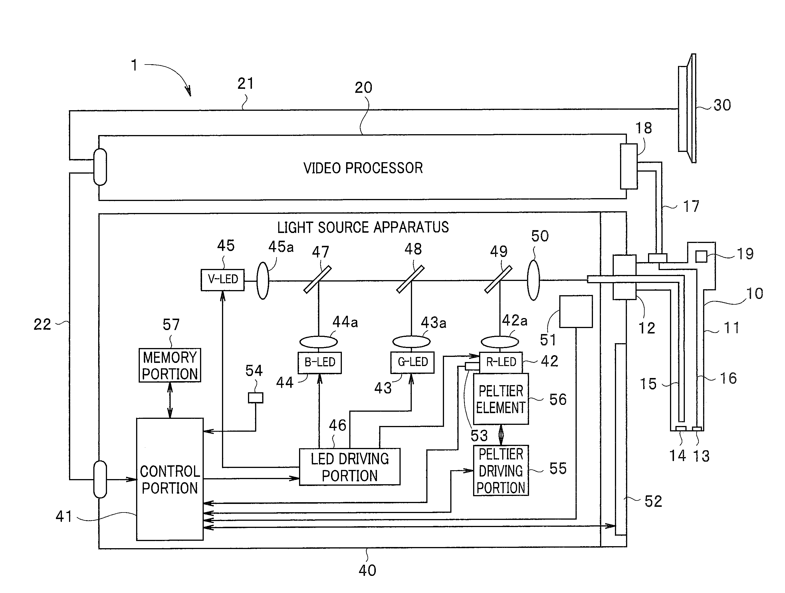
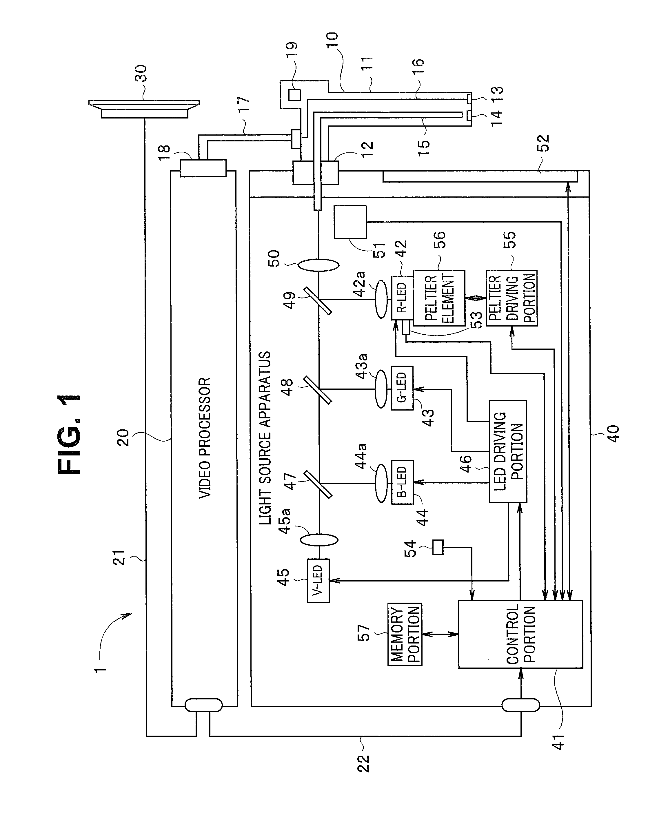
[0025]FIG. 1 is a block diagram showing a light source apparatus according to a first embodiment of the present invention. The present embodiment is such that the light source apparatus is applied to an endoscope apparatus having an endoscope, a video processor and a monitor.

[0026]An endoscope apparatus 1 is configured with an endoscope 10, a video processor 20, a monitor 30 and a light source apparatus 40. The endoscope 10 has an elongated insertion portion 11 which can be inserted into a lumen and the like at a distal end side, and its proximal end side is adapted to be detachably connected to the light source apparatus 40 via a connector 12.

[0027]Further, the endoscope 10 is adapted to be detachably connected to the video processor 20 via a cable 17 and a connector 18. Thus, different kinds of endoscopes can be connected to the light source apparatus 40 and the video processor 20.

[0028]An image pickup device 13 for picking up video of an object in a lumen or the like and a lens 1...

second embodiment

[0097]FIG. 10 is a flowchart adopted in a second embodiment of the present invention. In FIG. 10, same procedures as those in FIG. 6 are given same reference numerals, and description of the procedures will be omitted. A hardware configuration of the present embodiment is similar to FIG. 1. In the first embodiment, the control portion 41 determines a cooling ratio based on information about an amount-of-light ratio and controls power supply to cooling members for respective LEDs so that the determined cooling ratio is obtained. However, an amount of light which can be caused to be incident on or can be emitted from the light guide 15 used in the endoscope 10, is restricted depending on a kind or diameter of the light guide 15. Further, in order to prevent occurrence of halation when the image pickup device 13 performs image pickup also, it is necessary that an amount of emitted light of the light source apparatus 40 be restricted to be a predetermined maximum value (a maximum amount...


PUM


Abstract

An endoscope apparatus includes: first and second cooling units configured to cool first and second light source portions; an image pickup portion configured to generate a picked-up image; and a cooling control portion configured to control amounts of light emission of the light source portions while maintaining an amount-of-light ratio so that the brightness of the picked-up image becomes the target brightness and control cooling based on the information about the amount-of-light ratio and the brightness control information; wherein the cooling control portion decides a cooling capacity of the first cooling units and a cooling capacity of the second cooling units for cooling the respective light source portions for which the amounts of light emission are controlled, at the cooling ratio, so as to cause the light source portions to be included within a predetermined temperature range, based on the brightness control information.

Description

CROSS REFERENCE TO RELATED APPLICATION[0001]This application is a continuation application of PCT / JP2014 / 078223 filed on Oct. 23, 2014 and claims benefit of Japanese Application No. 2013-225778 filed in Japan on Oct. 30, 2013, the entire contents of which are incorporated herein by this reference.BACKGROUND OF THE INVENTION[0002]1. Field of the Invention[0003]The present invention relates to an endoscope apparatus appropriate for an endoscope.[0004]2. Description of the Related Art[0005]Conventionally, endoscope apparatuses for performing observation of a site to be examined or various kinds of treatments by inserting an elongated endoscope into a body cavity or the like have been widely used. In such an endoscope apparatus, a light source apparatus is adopted to perform photographing inside the cavity. In recent years, there may be a case where a light source apparatus adopting a solid-state light-emitting element, such as an LED and a laser light source, as a light emitting portio...

Claims


Application Information

Patent Timeline
Patent Type & Authority Applications(United States)
IPC IPC(8): A61B1/12A61B1/00A61B1/04A61B1/06A61B1/07
CPCA61B1/0638A61B1/128A61B1/0669A61B1/0684H01L33/64A61B1/04A61B1/07G02B23/2461G02B27/141A61B1/00006A61B1/044
Inventor SHIROTA, YUTAKATAKAHASHI, TOMOYATODA, MASATOYABE, YUSUKEYOSHIDA, YUSUKESAKAI, AIKOMASAKI, TAKAHIROHAYAMA, TAKAHIROMACHIDA, RYOOMORI, KOJI
Owner OLYMPUS CORP
Why Eureka
Try Eureka