

Three-Dimensional Shaping Method
a three-dimensional shaping and shape technology, applied in the field of three-dimensional shape making, can solve the problems of wasting a great amount of time, affecting the quality of the finished product, and being unavoidable of many appearances
- Summary
- Abstract
- Description
- Claims
- Application Information
AI Technical Summary
Benefits of technology
Problems solved by technology
Method used
Image

Examples
example 1
[0081]In the basic configuration (1)-2, when the diameter of an optical beam in the vicinity of the coordinate region is given as d mm, the width between scanning lines associated with folding-back of the optical beam is given as w mm, and the number of parallel traveling lines associated with folding-back of the optical beam is given as N, Example 1 is characterized in that the length of the shaping path formed for each of the optical beams is expressed by the formula shown below.
N{π(1−d2 / 4)−(N−1)wd} / {(N−1)w+d}mm [Formula 1]
[0082]The reason for the length of the shaping path expressed by the formula shown below is as follows:
N{π(1−d2 / 4)−(N−1)wd} / {(N−1)w+d}mm [Formula 2]
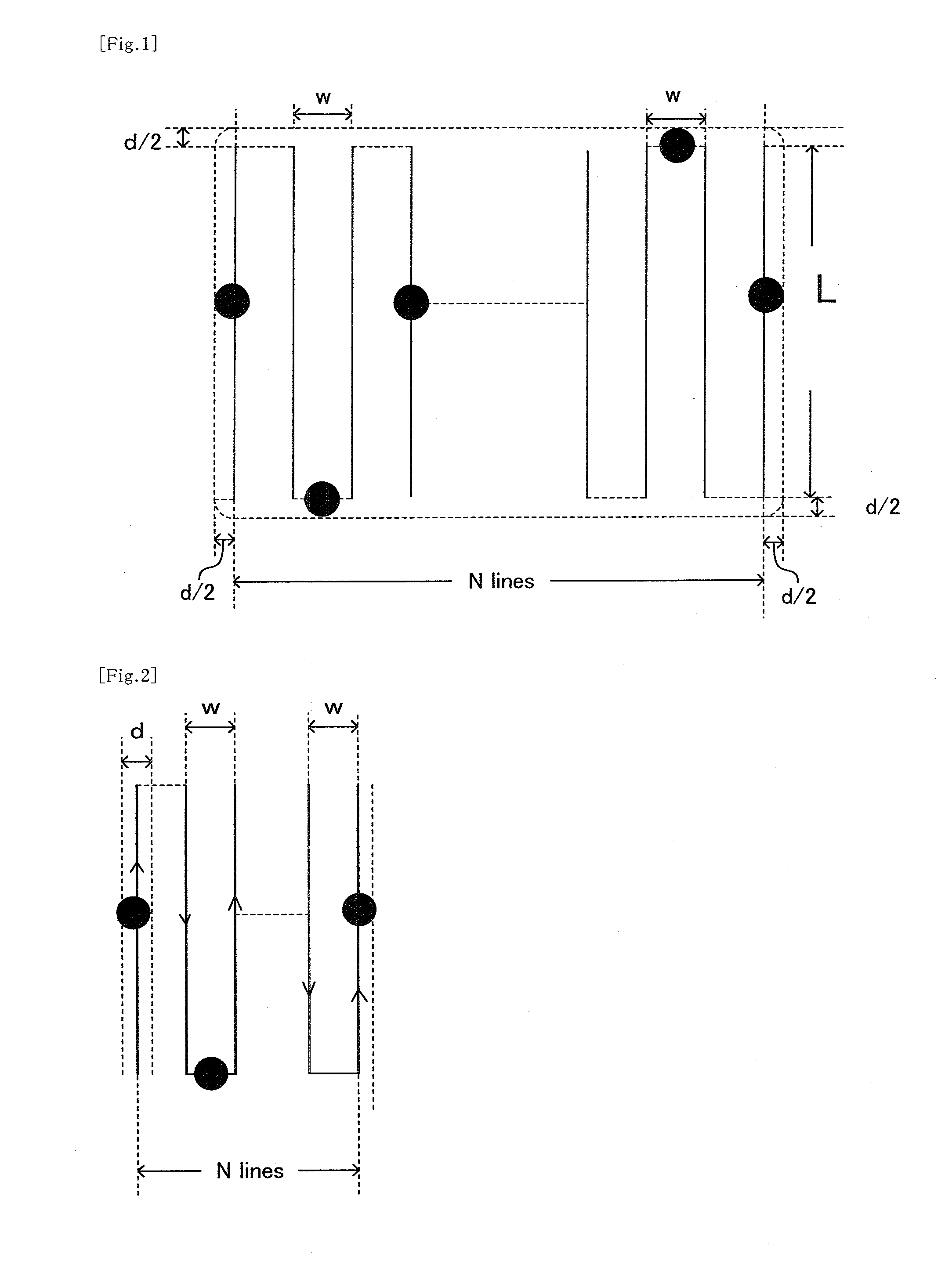
[0083]As shown in FIG. 1, in the case that a mean length of the N lines traveling in parallel is L mm, a width of the region surrounded by lines on both sides along the direction orthogonal to the parallel direction is expressed as (N−1)w.
[0084]As shown in FIG. 1, each of the (N−1) folding-back regions projects onl...
example 2
[0091]In the basic configuration (2)-2, Example 2 is characterized in that where a diameter of an optical beam is given as d mm and a width between scanning lines associated with the folded-back optical beam is given as w mm, the number of the lines in the sintered region 11 is a maximum value of integer in terms of a numerical value of 1+(2−d) / w.
[0092]The reason for the formula shown below established as the shaping width can be explained as follows with reference to FIG. 2.
1+(2−d) [Formula 6]
[0093]As apparent from FIG. 2, a width of the sintered region 11 formed by N traveling lines of parallel optical beams is expressed as (N−1)w+d.
[0094]Therefore, as described in the basic configuration (2)-1, where 2 mm is set as an ordinarily adopted baseline in which the shaping width is equal to or less than a predetermined extent, the formula shown below is established,
(N−1)w+d=2 [Formula 7]
and the formula shown below can be obtained.
N=1+(2−d) / w [Formula 8]
example 3
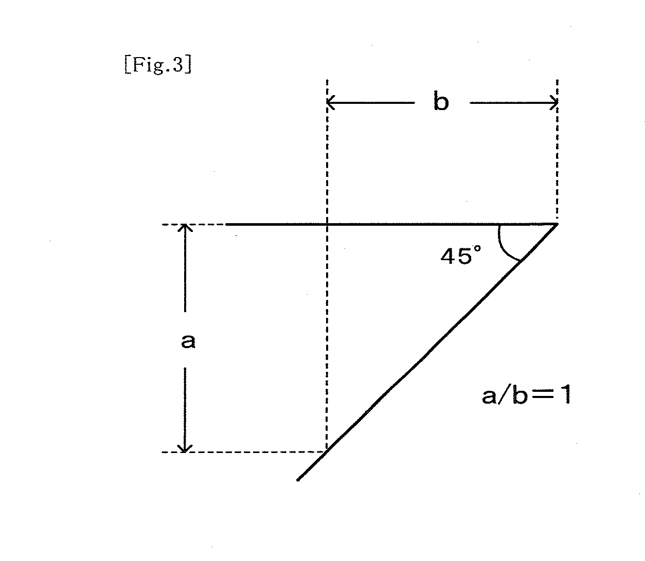
[0095]In the basic configuration (3)-2, Example 3 is characterized in that a ratio which is obtained by dividing a height width between both ends by a horizontal width is 1:1.
[0096]The grounds thereof are demonstrated by the fact that, as shown in FIG. 3, the undercut angle forms 45 degrees when the ratio is 1:1.
Effect of the Invention
[0097]In the present invention which is composed of the basic configurations (1)-1, -2, (2)-1, -2 and (3)-1, -2, a cause for forming a raised sintered portion on each layer is detected in advance efficiently and reliably, and the sintered portion is cut entirely or partially by a rotating cutting tool in a stage before the formation of a next layer positioned on the upper side of the layer concerned. Thereby, it is possible to prevent in advance problems in forming a powder layer on a next layer positioned on the upper side of the layer concerned.
[0098]The three-dimensional shaping method of the present invention is able to provide efficient shaping wi...
PUM
| Property | Measurement | Unit |
|---|---|---|
| width | aaaaa | aaaaa |
| angle | aaaaa | aaaaa |
| mean diameter | aaaaa | aaaaa |
Abstract
Description
Claims
Application Information