Vehicle flow-regulating structure

Inactive Publication Date: 2016-08-18
TOYOTA JIDOSHA KK
View PDF15 Cites 22 Cited by
  • Summary
  • Abstract
  • Description
  • Claims
  • Application Information

AI Technical Summary

Benefits of technology

[0018]The vehicle flow-regulating structure according to the first aspect of the present invention obtains an excellent advantageous effect of enabling the aerodynamic performance and NV performance of the vehicle including the surrounding information detection section on the roof to be improved.
[0019]The vehicle flow-regulating structure according to the second aspect of the present invention obtains an excellent advantageous effect of enabling the aerodynamic performance and NV performance of the vehicle to be improved by the roof visor.
[0020]The vehicle flow-regulating structure according to the third aspect of the present in

Problems solved by technology

However, the above-described conventional example does not particularly take airflow or noise and vibration (NV) performance in a

Method used


Image

  • Vehicle flow-regulating structure
  • Vehicle flow-regulating structure
  • Vehicle flow-regulating structure

Examples


first exemplary embodiment

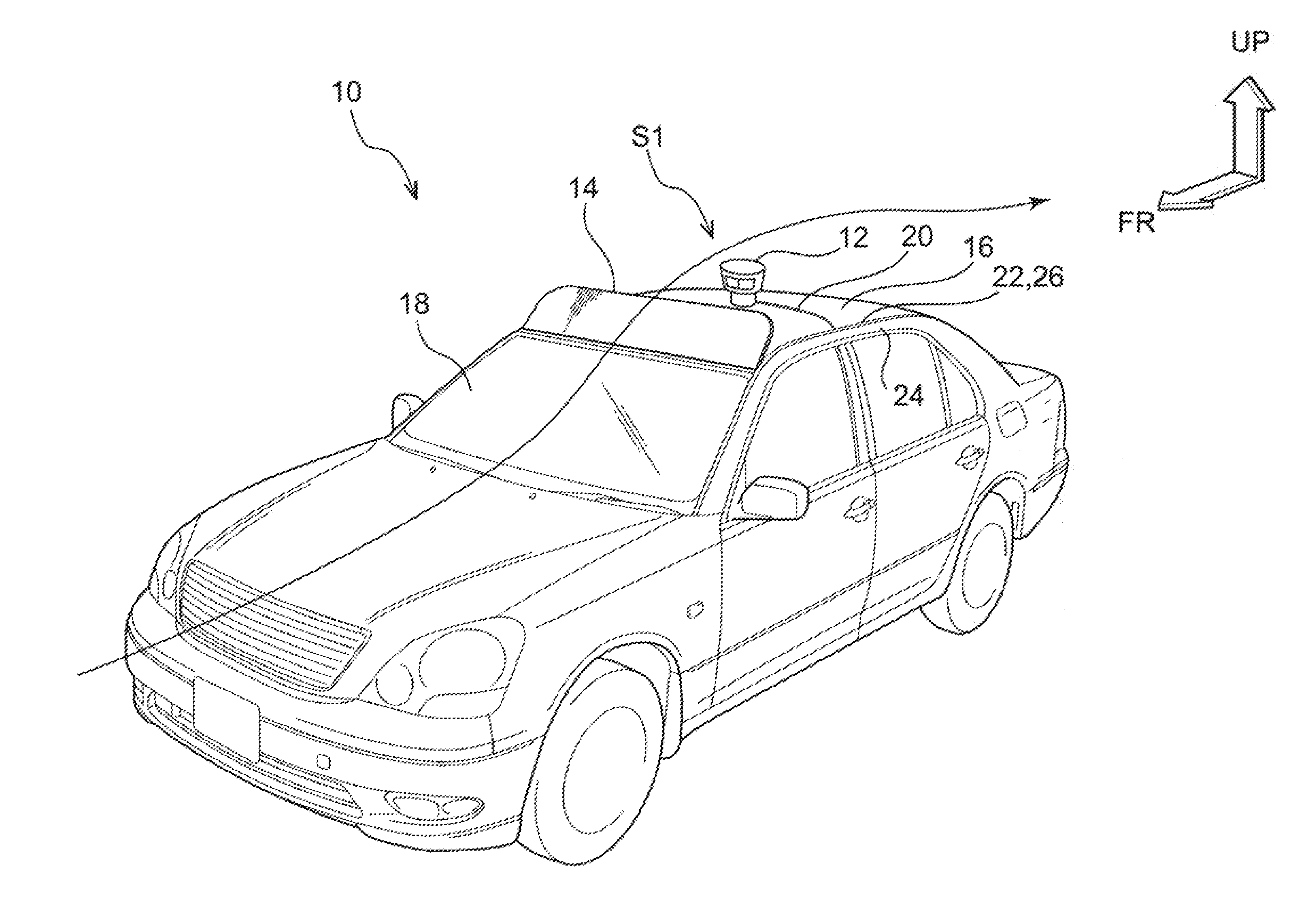
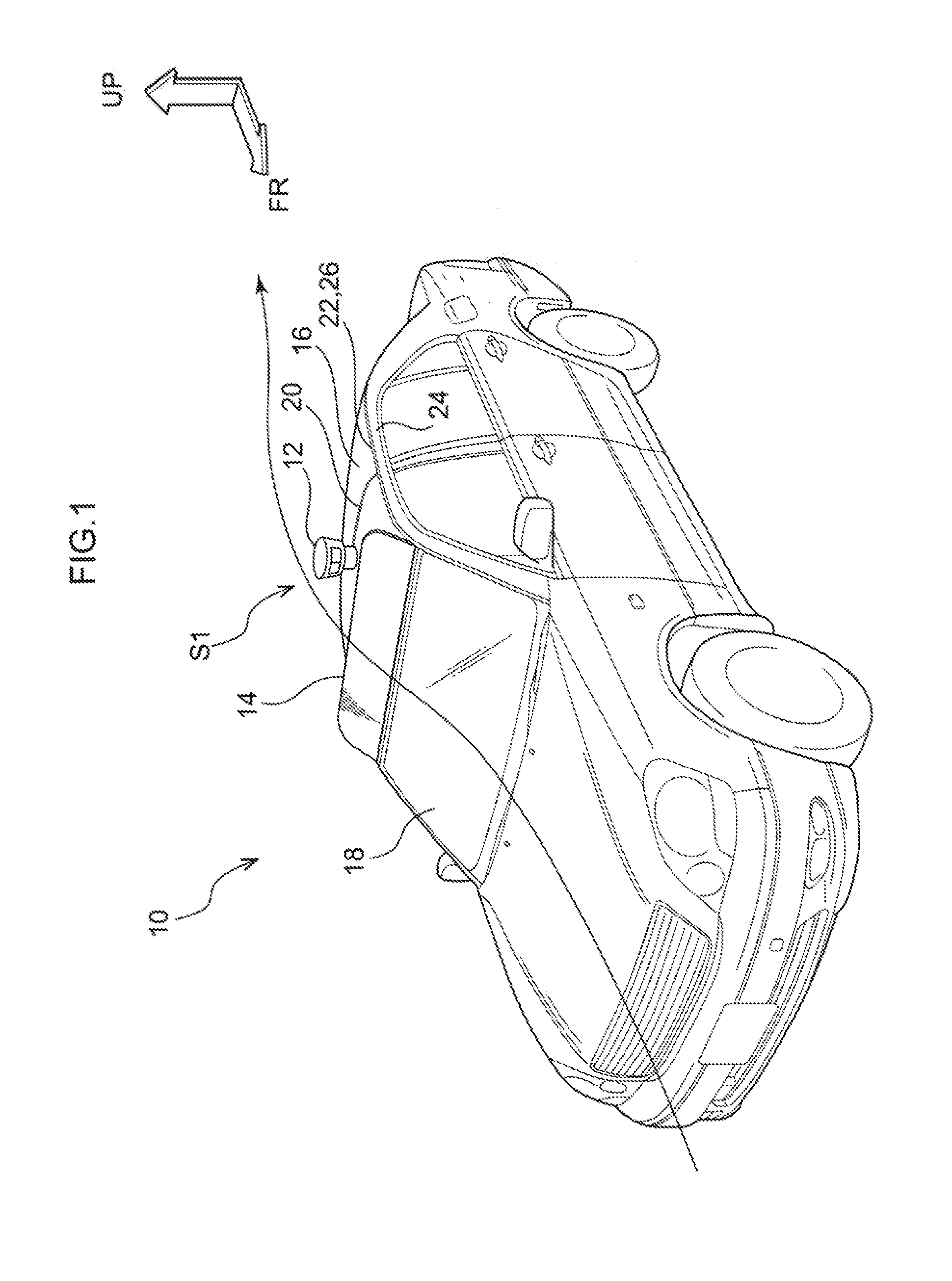
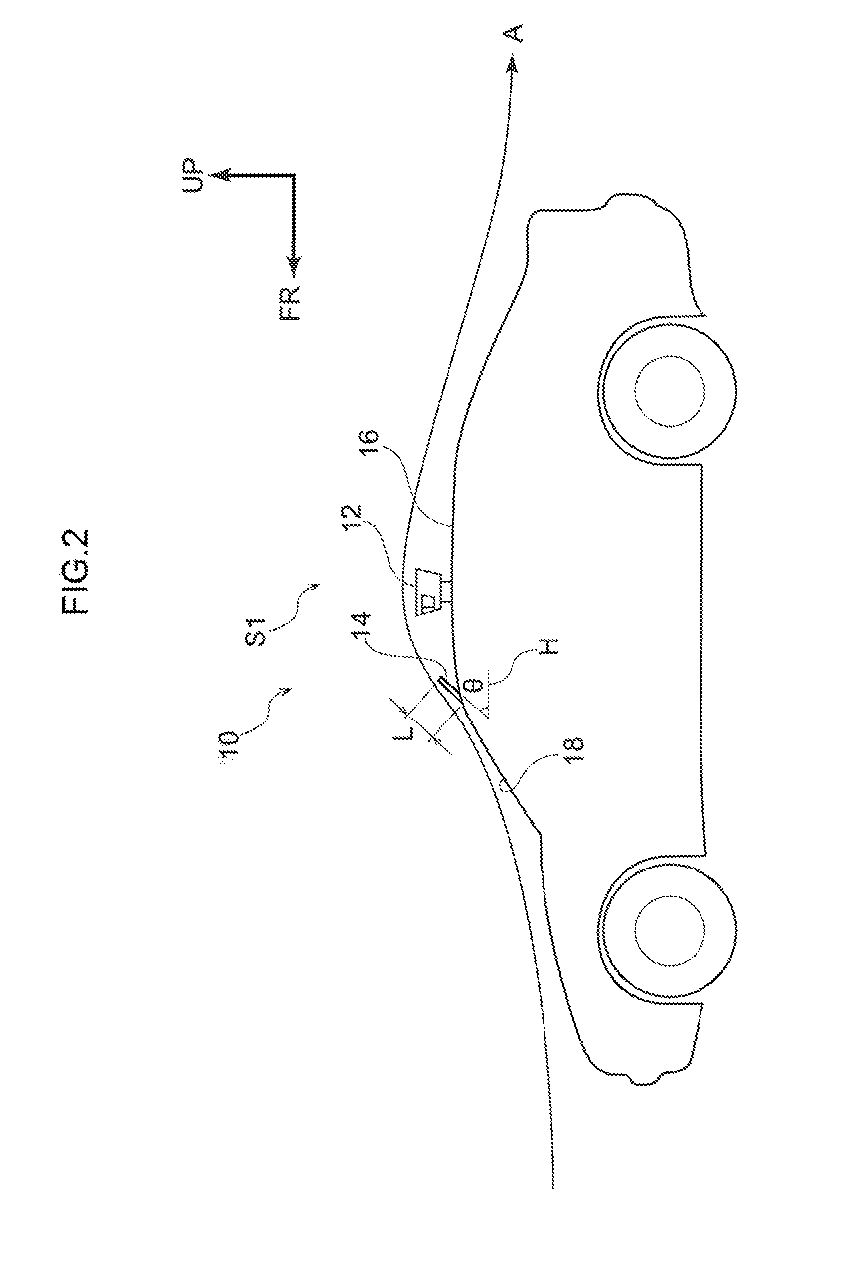
[0030]In FIG. 1 and FIG. 2, a vehicle flow-regulating structure S1 according to an exemplary embodiment is employed in an autonomous vehicle 10, for example, and includes a surrounding information detection section 12, and a roof visor 14 that is an example of a flow-regulating means.

[0031]The surrounding information detection section 12 is millimeter-wave radar, microwave radar, laser radar, an infrared sensor, an ultrasonic sensor, an optical camera, or the like, which is provided on a roof 16 of the vehicle 10, and detects surrounding information of the vehicle 10. The surrounding information detection section 12 is provided at a center portion of the roof 16, for example, and detects surrounding information of the vehicle 10 while rotating 360 degrees with its rotation axis along the vehicle up-down direction.

[0032]Although not illustrated in the drawings, the vehicle 10 is provided with a travel planning section and a travel control section. The travel planning section generate...

second exemplary embodiment

[0044]In a vehicle flow-regulating structure S2 according to an exemplary embodiment in FIG. 5 and FIG. 6, surrounding information detection sections 32 that are at least part of a surrounding information detection section are respectively incorporated in front end portions 30A of roof rails 30. Each front end portion 30A is an example of a flow-regulating means, and is formed in a streamlined shape, for example. A pair of the roof rails 30 are provided on the roof 16 of the vehicle 10 at the left and right thereof, and extend along the vehicle front-rear direction.

[0045]Each surrounding information detection section 32 is a sensor such as a camera, and is provided inside a cover 34 at the front end portion 30A of the roof rail 30. The cover 34 is formed in a streamlined shape so as to be integral to the front end portion 30A of the roof rail 30. In cases in which the surrounding information detection section 32 is an optical sensor, the cover 34 is configured to be transparent. In ...


PUM


Abstract

A vehicle flow-regulating structure includes a surrounding information detection section that is provided on a roof of a vehicle and that detects surrounding information of the vehicle, and a roof visor (a flow-regulating means) that is provided on the roof and that regulates airflow at the surrounding information detection section while the vehicle is travelling.

Description

CROSS-REFERENCE TO RELATED APPLICATION[0001]This application claims priority under 35 USC 119 from Japanese Patent Application No. 2015-28057 filed on Feb. 16, 2015, the disclosure of which is incorporated by reference herein.BACKGROUND[0002]1. Technical Field[0003]The present invention relates to a vehicle flow-regulating structure.[0004]2. Description of the Related Art[0005]Japanese Patent Application Laid-Open (JP-A) No. 2005-291808 describes a structure in which a sensor such as a camera or radar is mounted on a roof of an autonomous vehicle.SUMMARY OF THE INVENTION[0006]However, the above-described conventional example does not particularly take airflow or noise and vibration (NV) performance in a vicinity of the sensor (surrounding information detection section) on the roof while the vehicle is travelling into consideration.[0007]An object of an exemplary embodiment of the present invention is to improve aerodynamic performance and NV performance in vehicles including a surro...

Claims


Application Information

Patent Timeline
IPC IPC(8): B62D35/00
CPCB62D35/00B62D29/008
Inventor SHIRAI, YASUHIRO
Owner TOYOTA JIDOSHA KK
Why Eureka
Try Eureka