
Color Correction Method for Optical See-Through Displays

a color correction method and display technology, applied in the field of color correction methods for optical see-through displays, can solve the problems of reducing the readability of text, reducing the usability of such devices, and reducing the usability of background [4]

Inactive Publication Date: 2016-08-18
UNIVERSITY OF MANITOBA
View PDF9 Cites 39 Cited by
  • Summary
  • Abstract
  • Description
  • Claims
  • Application Information

AI Technical Summary

Benefits of technology

The patent text describes a method for accurately color correcting display screens. It takes into account two types of distortion: render and material. By characterizing these distortions, the method can predict how colors will blend on the screen, resulting in a more accurate color correction. The method also works better for displays with limited color profiles and low luminosity backgrounds, and is harder for high luminosity backgrounds. Overall, this approach allows for more precise and accurate color correction for various display screens.

Problems solved by technology

Color blending is an important issue as it affects the legibility and color—encodings of digital information and compromises the general us—ability of such devices.
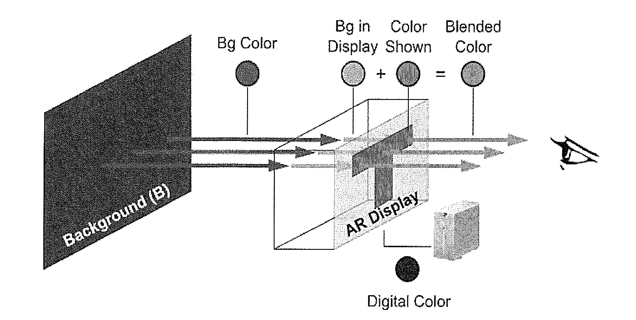
The perception of color as a blend of the display color and the background [4] can be a major usability problem in optical head-mounted displays (OHMD).
Color blending has several negative effects on the display content it reduces the readability of text [18], makes augmented reality (AR) objects look translucent and unreal [1], Impairs the interpretation of color-encoded information such as status icons or system alerts, and leads users to confusion [19].
Therefore, addressing color blending is an important issue as it compromises the usability and adoption of OHMDs [10][11].
Occlusion support requires additional optical hardware, making the OHMD bulky [3][5] and compromising its transparency [14].
However, existing color correction algorithms are not usable.

Method used


Image

  • Color Correction Method for Optical See-Through Displays
  • Color Correction Method for Optical See-Through Displays
  • Color Correction Method for Optical See-Through Displays

Examples


Embodiment Construction

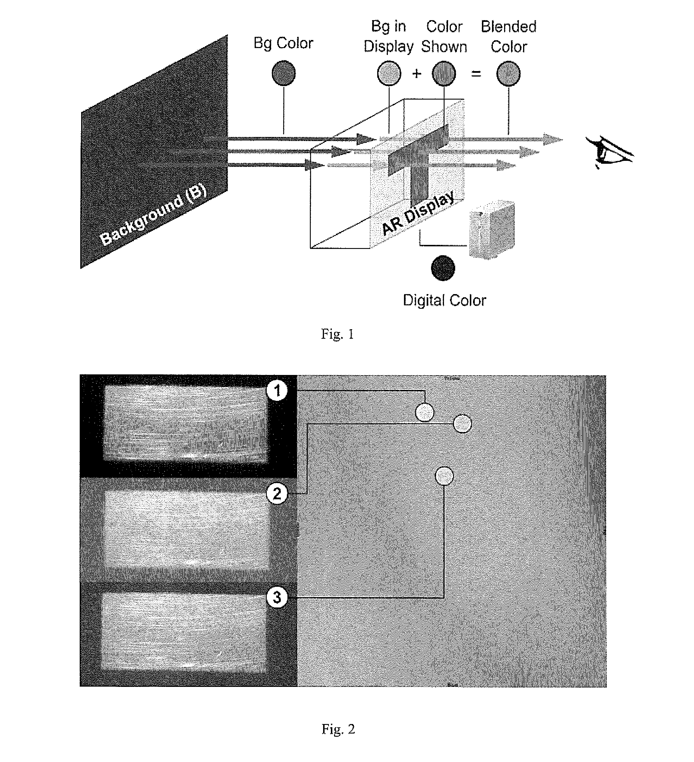
[0109]In optical see-through displays, light coming from background objects mixes with the light originating from the display, causing what is known as the color blending problem. Color blending negatively affects the usability of such displays as it impacts the legibility and color encodings of digital content. Color correction alms at reducing the impact of color blending by finding an alternative display color which, once mixed with the background, results in the color originally intended.

[0110]In this specification we model color blending based on two distortions induced by the optical see-through display. The render distortion explains how the display renders colors. The material distortion explains how background colors are changed by the display material. We show the render distortion has a higher impact on color blending and propose binned-profiles (BP) descriptors of how a display renders colors to address it. Results show that color blending pre-dictions using BP have a lo...


PUM


Abstract

In a method of correcting a desired color of a pixel to be displayed in an optical see-through display, a binned-display profile of prescribed colors arranged to be rendered by the display include background colors added to it so that the desired color can be matched to a closest one of the resulting predicted color profile of colors which are predicted to be perceived by a user. The display is then instructed to display the prescribed color which corresponds with the closest matching predicted color such that an observer substantially perceives the desired color. Typically the desired color is only compared to a subset of the predicted colors for efficiency. Additional corrections may take place to improve contrast of graphical content compared to the background in some instance.

Description

FIELD OF THE INVENTION[0001]The present invention relates to a method of accurately representing color on an optical see-through display by considering both how the display renders color and how the color of the background affects the perception of color by a user. The present invention further relates to additional corrections of the color to be display to ensure sufficient contrast between graphical items to be display and the background visible through the display.BACKGROUND[0002]Optical see-through (OST) displays allow users to view digital content and physical objects simultaneously. They come in multiple form factors (e.g. head mounted displays, projection-based and transparent LCD and OLEDs) and are widely used in augmented reality (AR) applications including medical, maintenance, education and training (see [Bimber and Raskar 2005][Carmigniani et al. 2011] for a comprehensive list of applications). OST displays can be additive (have their own light source e.g. projection-bas...

Claims


Application Information

Patent Timeline
Patent Type & Authority Applications(United States)
IPC IPC(8): G09G3/20
CPCG09G5/02G02B27/017G02B2027/0112G09G3/2003G09G2320/0242G09G2340/06G09G2340/10G02B2027/014G09G3/002G09G5/026G09G5/06G09G2340/14G09G2380/10
Inventor SRIDHARAN, SRIKANTH KIRSHNAMACHARIRAMOS, JUAN DAVID HINCAPIEIRANI, POURANG
Owner UNIVERSITY OF MANITOBA
Learn More