Device and method for mounting a sensor and for sealing a cabinet

a sensor and cabinet technology, applied in the field of devices for mounting sensors and sealing cabinets, can solve the problems of sensor damage, sensor collapse, sensor failure, etc., and achieve the effect of high position accuracy

Inactive Publication Date: 2016-08-25
COMMSCOPE TELECOMM (SHANGHAI) CO LTD +2
View PDF3 Cites 5 Cited by
  • Summary
  • Abstract
  • Description
  • Claims
  • Application Information

AI Technical Summary

Benefits of technology

[0009]Accordingly, it is an object of the present invention to provide a device for mounting a sensor, which does not require the sensor to be mounted in high position accuracy.
[0010]Accordingly, it is another object of the present invention to provide a device for mounting a sensor, which ensures that the sensor can still work normally under an overlarge external action force or an overlarge external action displacement.
[0028]In the various embodiments of the present invention, when an overlarge external action force beyond the initial deformation force (that is, a protection force for the sensor) F0 or an overlarge external action displacement beyond the maximum stroke of the sensing contact is applied on the sensor, the sensor is moved relative to the bracket along the support rod against the elastic element. Since the elastic element can provide an elastic buffer distance for the sensor, it reduces the request for the initial mounting position accuracy of the sensor, and ensures that the sensor can still work normally under the overlarge external action force or the overlarge external action displacement.

Problems solved by technology

For some fine sensors, for example, a micro electromechanical sensor or a fiber optic sensor, an overlarge external action force may cause the internal structure of the sensor to collapse and fail.
Further, if the sensor is mounted in poor position accuracy, the external action displacement applied on a sensing contact of the sensor may be beyond the maximum stroke of the sensing contact, and the sensor may be ruined.

Method used


Image

  • Device and method for mounting a sensor and for sealing a cabinet
  • Device and method for mounting a sensor and for sealing a cabinet
  • Device and method for mounting a sensor and for sealing a cabinet

Examples


Embodiment Construction

[0036]Exemplary embodiments of the present disclosure will be described hereinafter in detail with reference to the attached drawings, wherein the like reference numerals refer to the like elements. The present disclosure may, however, be embodied in many different forms and should not be construed as being limited to the embodiment set forth herein; rather, these embodiments are provided so that the present disclosure will be thorough and complete, and will fully convey the concept of the disclosure to those skilled in the art.

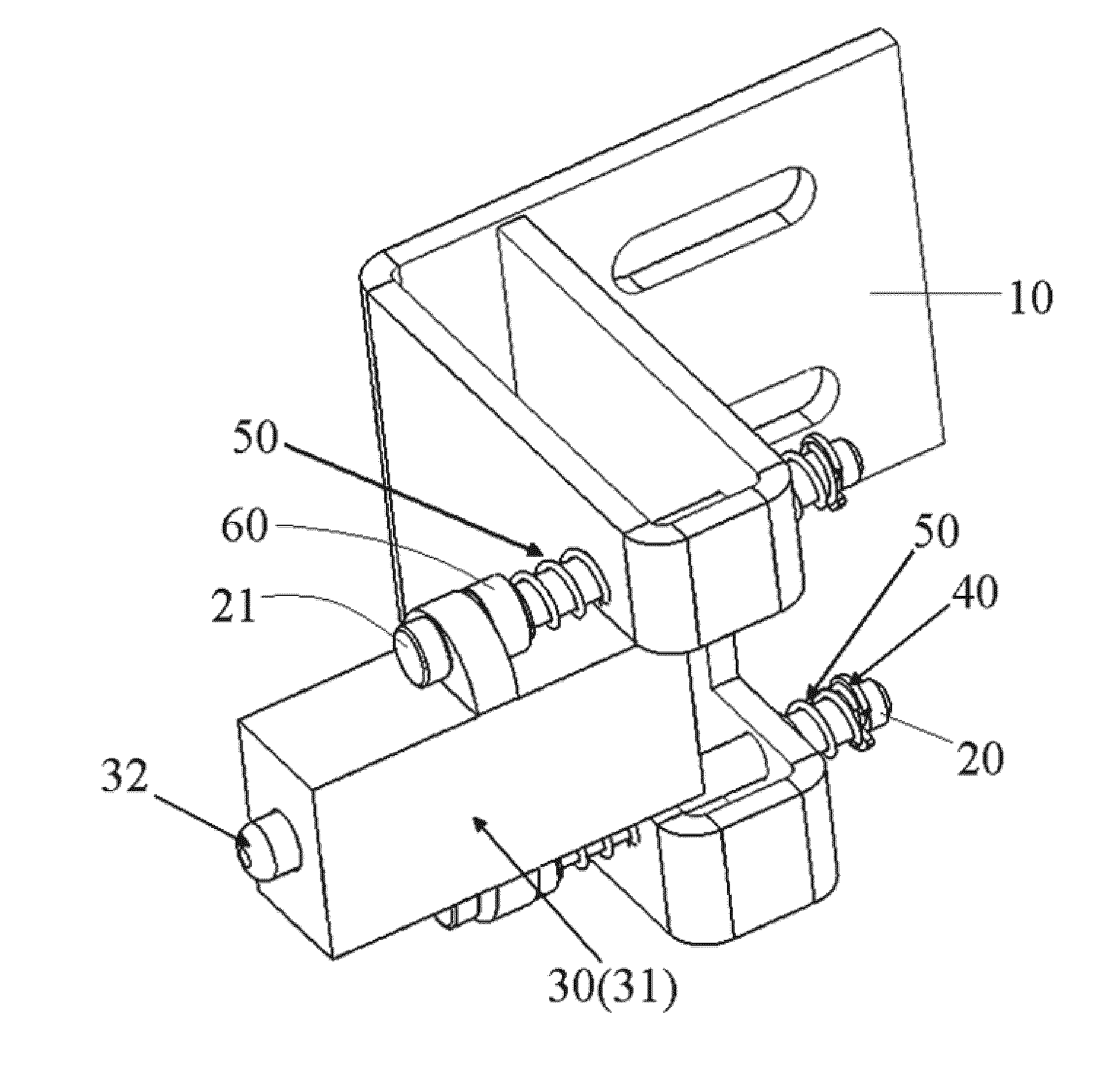
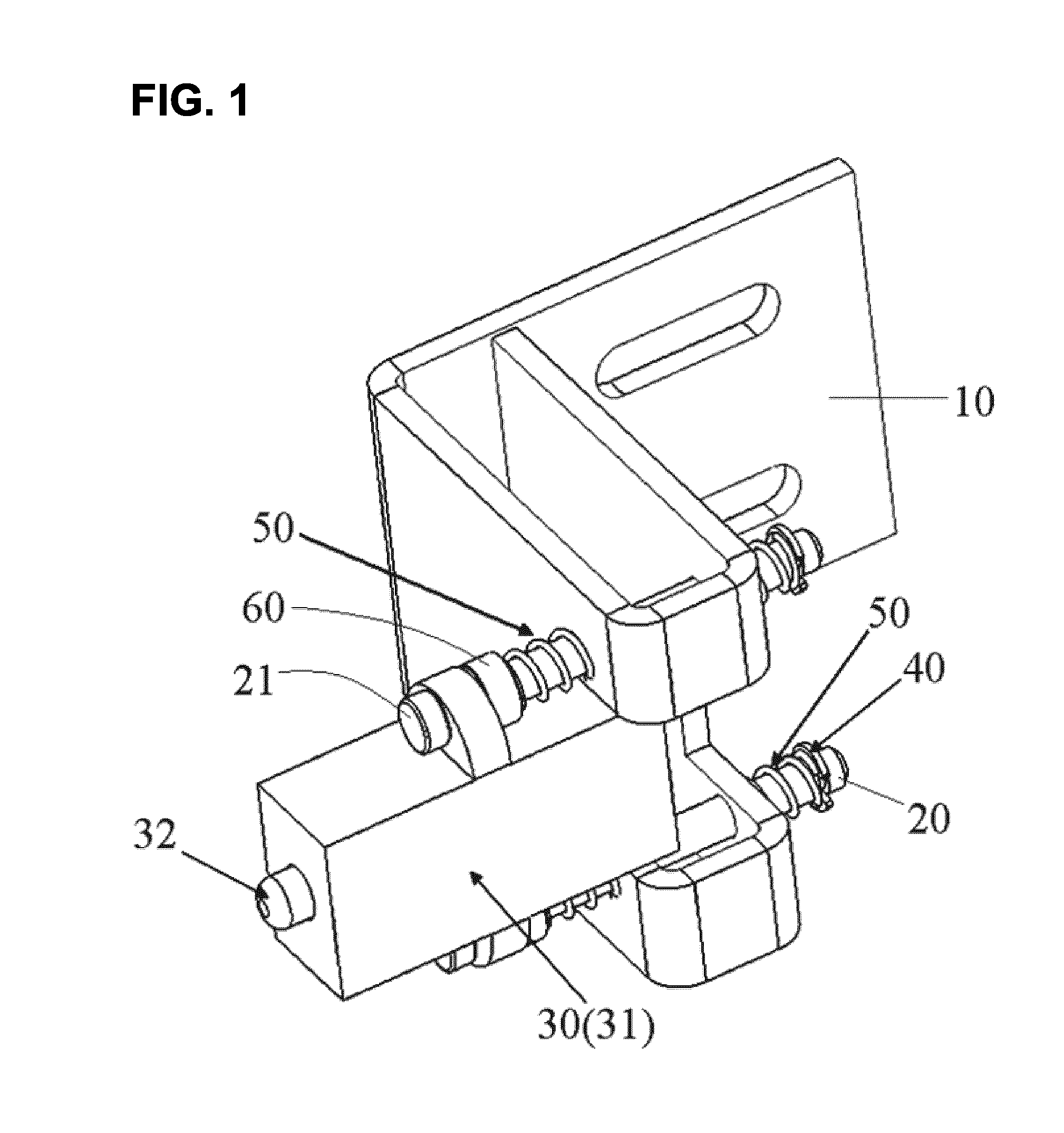
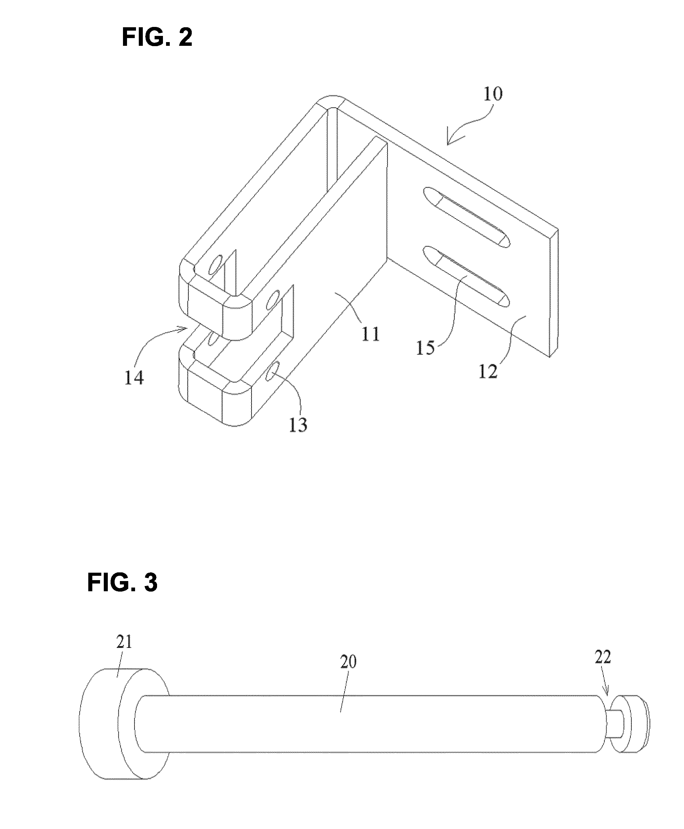
[0037]FIG. 1 is an illustrative perspective view of a device for mounting a sensor 30 according to an exemplary embodiment of the present invention; FIG. 2 is an illustrative perspective view of a bracket 10 of the device of FIG. 1; FIG. 3 is an illustrative perspective view of a support rod 20 of the device of FIG. 1.

[0038]As shown in FIGS. 1-3, in an exemplary embodiment of the present invention, there is provided a device for mounting a sensor 30, comprisi...


PUM


Abstract

A device for mounting a sensor, comprising: a bracket formed with at least one guide hole therein; at least one support rod each passing through a mounting hole in a housing of the sensor and the guide hole in the bracket and mounted on the housing of the sensor and the bracket; and at least one elastic element each disposed on the support rod, so that the sensor is movable relative to the bracket along the support rod against the elastic element. Other brackets can be used. The sensor senses when a cabinet door is closed and sealed.

Description

CROSS-REFERENCE TO RELATED APPLICATIONS[0001]This application claims the benefit of Chinese Patent Application No. 201310441909.6, filed on Sep. 25, 2013; Chinese Utility Model Application No. 201320594217.0, filed on Sep. 25, 2013; and U.S. Provisional Application No. 61 / 953,509, filed Mar. 14, 2014, the disclosures of which are incorporated by reference.[0002]1. Field of the Invention[0003]The present invention relates to a device for mounting a sensor and for sealing a cabinet.[0004]2. Description of the Related Art[0005]In the prior art, a contact sensor is often rigidly fixed on a stationary frame, and the contact sensor is not movable relative to the stationary frame. Thereby, the contact sensor must be mounted in a high position accuracy to ensure an external action displacement applied on a sensing contact of the sensor within a maximum stroke (a safe stroke) of the sensing contact. Furthermore, the contact sensor must have an enough mechanical strength to bear an overlarge ...

Claims


Application Information

Patent Timeline
Patent Type & Authority Applications(United States)
IPC IPC(8): A47B97/00G01D11/24G01D11/30F16M13/02
CPCF25D2700/02F25D29/005G01D11/30A47B2220/0091G01D11/245F16M13/02A47B97/00G01D11/24
Inventor VASTMANS, KRISTOFBOMBERA, MOJMIRLIN, LIN
Owner COMMSCOPE TELECOMM (SHANGHAI) CO LTD
Why Eureka
Try Eureka