Tank with internal connecting member and method for assembling such a tank

a technology of connecting member and tank, which is applied in the direction of mechanical equipment, machines/engines, transportation and packaging, etc., can solve the problems of complex and delicate operation, need for complex welding tools, etc., and achieve the effect of less complicated assembly operation and more robust operation

Active Publication Date: 2016-08-25
PLASTIC OMNIUM ADVANCED INNOVATION & RES SA
View PDF0 Cites 2 Cited by
  • Summary
  • Abstract
  • Description
  • Claims
  • Application Information

AI Technical Summary

Benefits of technology

[0004]The object of embodiments of the invention is to provide a method for assembling a tank which is more robust and requires a less complicated assembly operation compared to the prior art solutions. Another object of the invention is to provide a tank that may be assembled using a reliable and simple assembly method.

Problems solved by technology

In the case of welding this is a complex and delicate operation as the first and second pillar or wall parts are not easily accessible.
The reinforcement pillars or walls are typically at a distance from the perimeter welding path of the first and second shells, resulting in the need for complex welding tools.

Method used


Image

  • Tank with internal connecting member and method for assembling such a tank
  • Tank with internal connecting member and method for assembling such a tank
  • Tank with internal connecting member and method for assembling such a tank

Examples


first embodiment

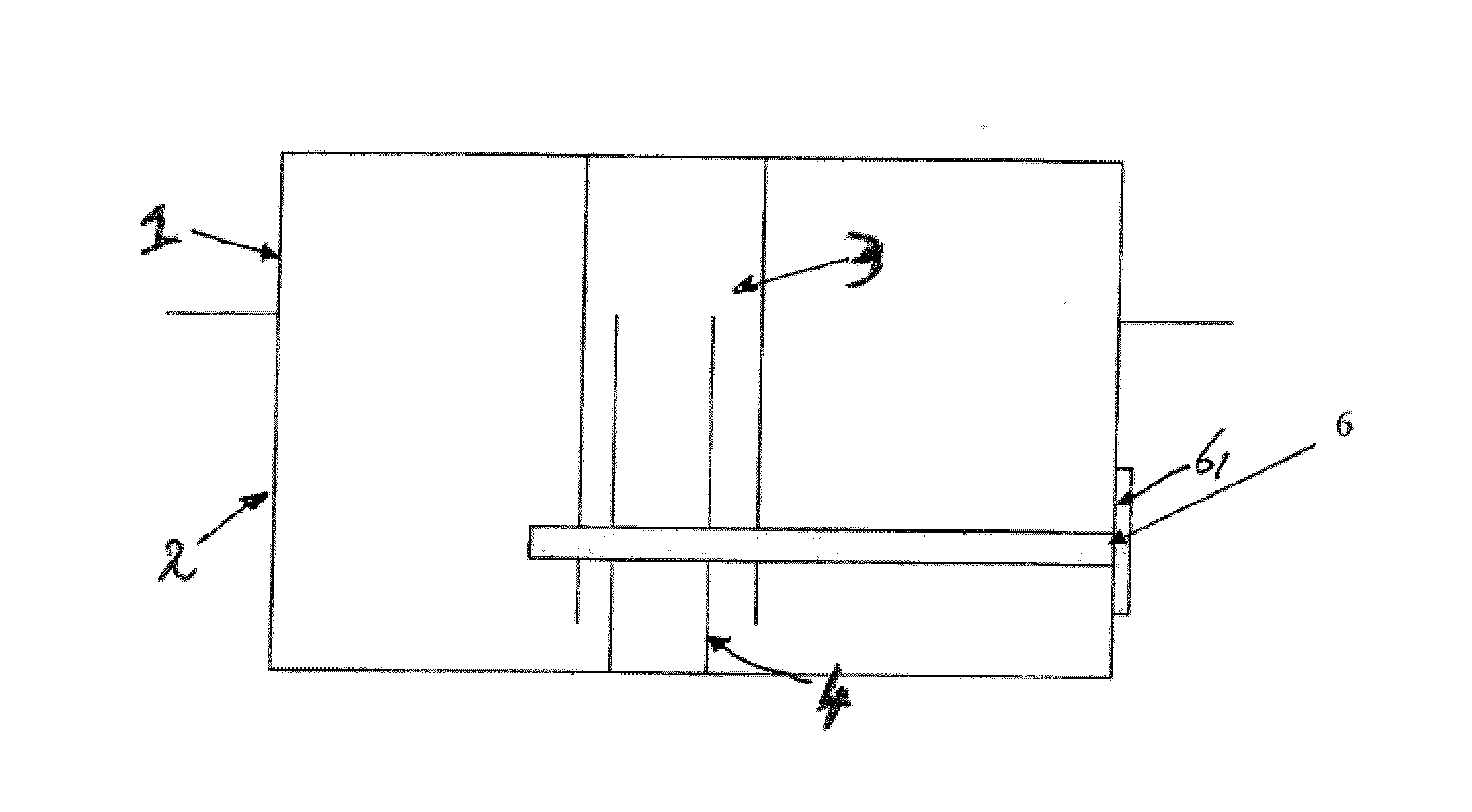
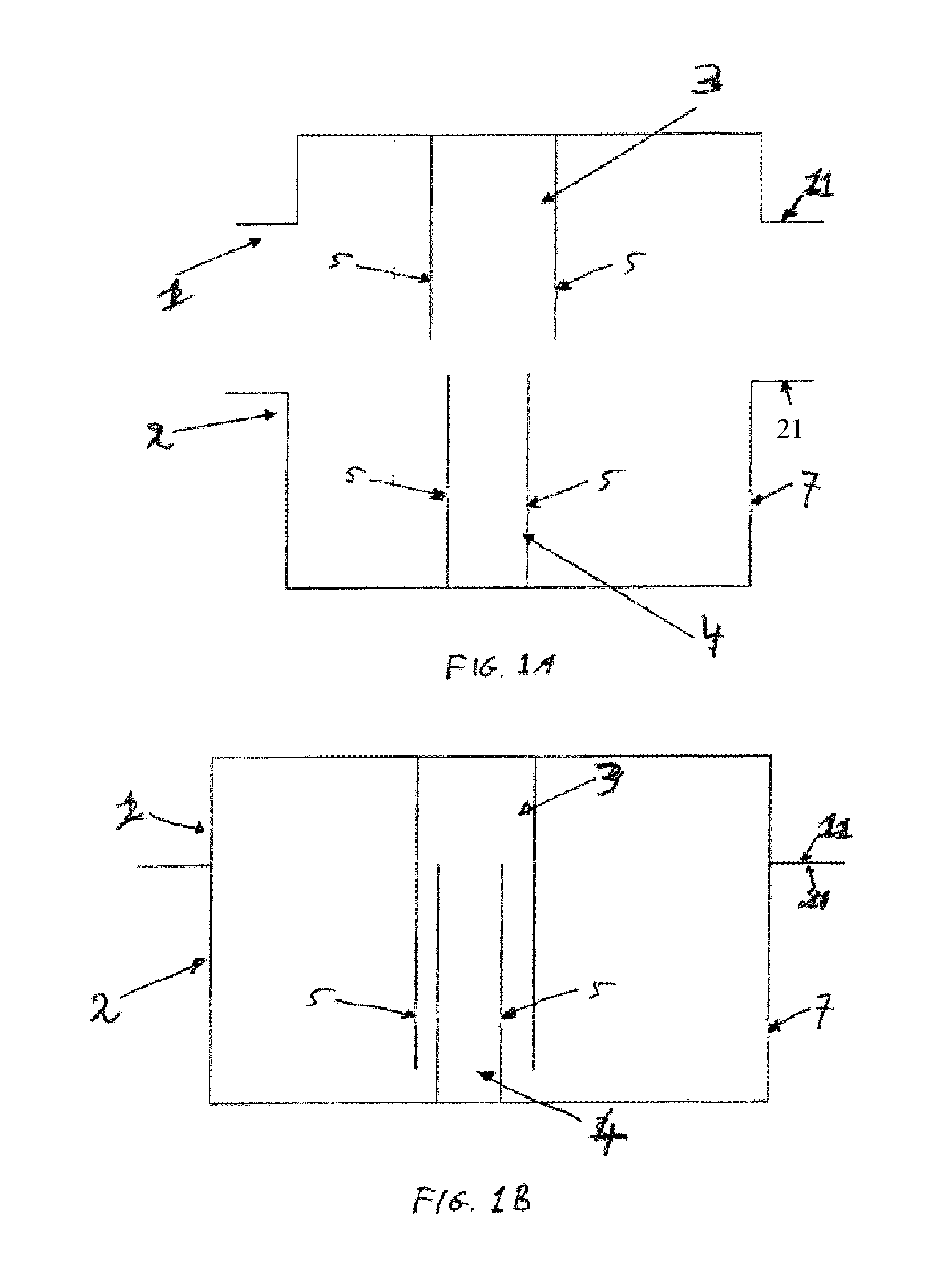
[0039]FIGS. 1A-1C illustrate schematically a tank and method of the invention. The tank is assembled from a plastic top shell 1 having a flange 11 around its edge and a plastic bottom shell 2 having a flange 21 around its edge. Flange 11 mirrors flange 21. In another embodiment the flanges 11 and 21 can have different shape and size. For example, the flange 11 can have a greater surface than the flange 21.

[0040]A first elongated connecting member 3 functioning as a reinforcement member extends from and is integrated in a top wall portion of the top shell 1. A second elongated connecting member 4 functioning as a reinforcement member extends from and is integrated in a bottom wall portion of the bottom shell 2. The connecting members 3, 4 are integrally moulded with the respective shells 1, 2.

[0041]The connecting members 3, 4 are tube shaped, wherein connecting member 3 has a larger diameter than connecting member 4. The term “tube shaped” should be interpreted as having any hollow c...

second embodiment

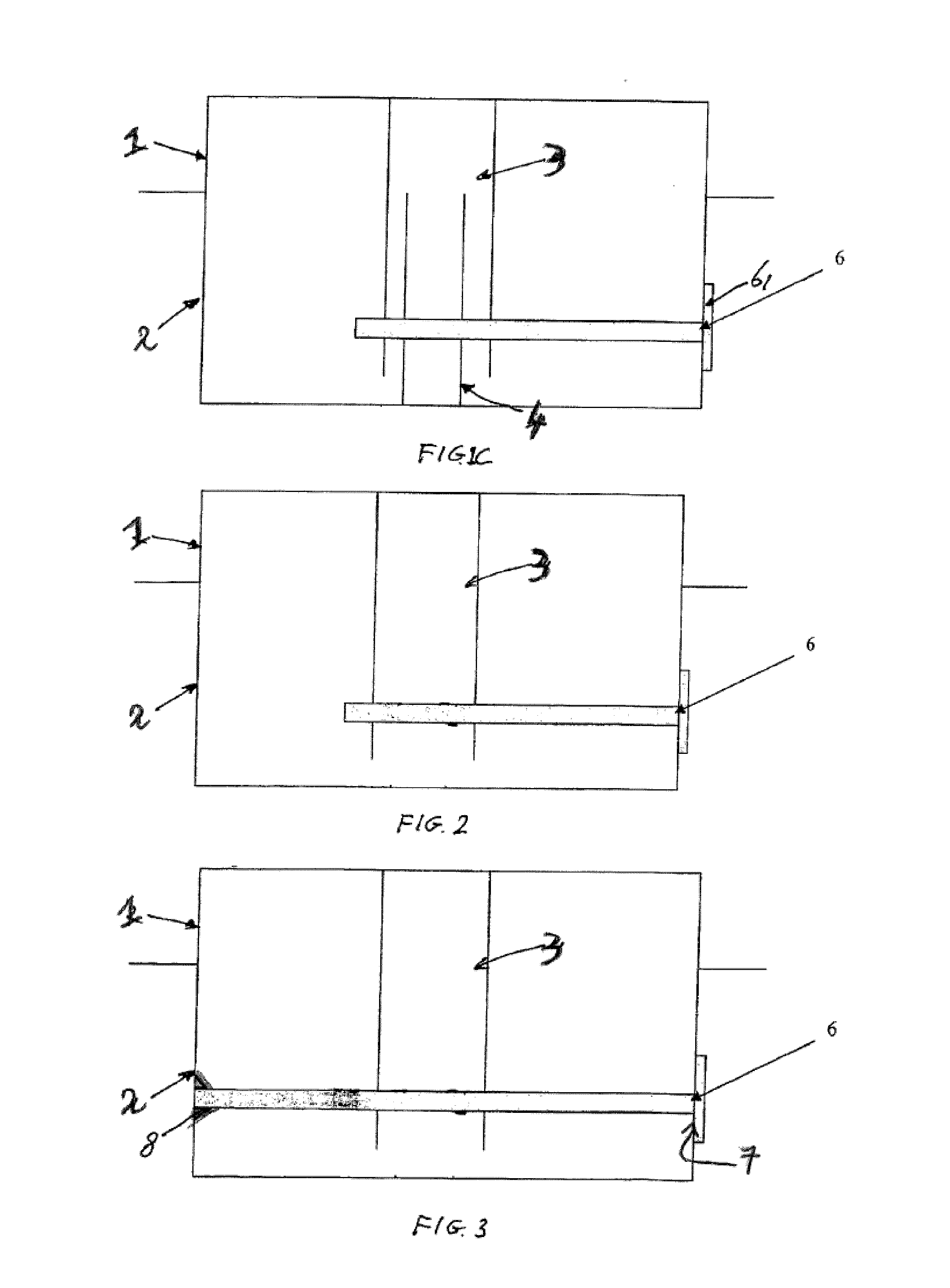
[0045]In a second embodiment as shown in FIG. 2, only one of the shells 1, 2, in this example the top shell 1, is provided with one or more connecting members 3 with holes 5 as described above. The pin 6 is inserted through hole 7 and holes 5 and fixed by flange 6 as described above, and is dimensioned such that it functions as a reinforcement member by itself in cooperation with the connecting member 4.

[0046]A third embodiment as shown in FIG. 3, is equal to the second embodiment, but the pin 6 is dimensioned such that it reaches to the opposite side wall of shell 2, where a receiving element 8 with a recess is integrated in the wall, such that the outer end of the pin 6 is inserted in said recess of the receiving element 8. Thereby bending of the pin 6 is prevented, such that the connecting member 4 is more securely locked in place. Alternatively the pin 6 may extend through a hole in the opposite side wall of shell 2 where it may be welded, e.g. by pushing a hot tool against the ...

fourth embodiment

[0048]A fourth embodiment is illustrated in FIG. 4. The first shell 1 is provided with two first connecting members 3 extending inwardly in the tank. The second shell is provided with a second connecting member 4. A first pin 6 extends through a first opening in a side wall of second shell 2 through a first set of aligned holes 5 in one first connecting member and the second connecting member. A second pin 6 extends through a second opening in a side wall of second shell 2 through a second set of aligned holes 5 in the other first connecting member and the second connecting member.

[0049]The connecting member(s) illustrated in the figures may be shaped to function as a reinforcement member(s) and / or may function as a tank accessory member for receiving therein and / or for supporting a tank accessory. If the connecting member is hollow, and if the interior of the connecting member communicates with the internal volume of the tanks, e.g. a level gauge, a pressure sensor, a valve, etc co...


PUM


Abstract

A method for assembling a tank including: providing a first shell and a second shell; putting edges of the first and second shells into contact with each other and mutually connecting the edges; providing the first shell with a first connecting member extending inwardly from an inner surface of the first shell, the first connecting member including a hole; and after the edges of the first and second shells are put into contact with each other, connecting the first connecting member to the second shell by inserting a pin shaped element through a hole in the second shell and the hole in the first connecting member.

Description

FIELD OF THE INVENTION[0001]The invention relates to a method for assembling a tank, in particular a fuel or an additive tank for a vehicle, comprising providing a first shell and a second shell, and putting the edges of said two shells into contact with each other and mutually connecting said edges such that said shells together form a substantially closed container delimiting an internal volume. The invention also relates to a tank.BACKGROUND[0002]Fuel tanks assembled from a two plastic shells are known, and may comprise a stabilizing column or wall in the internal volume of the tank in order to limit deformations of the tank. Traditionally fuel systems in passenger vehicles are designed to hold a specific amount of liquid fuel at a pressure essentially the same as the ambient pressure. With the introduction of Hybrid vehicles and more specifically Plug in Hybrids, which are designed such that they could potentially go several months without using fuel, it is in the interest of th...

Claims


Application Information

Patent Timeline
Patent Type & Authority Applications(United States)
IPC IPC(8): B60K15/03B60K15/035
CPCB60K15/03177B60K15/03006B60K15/035F01N2610/02B60K2015/03493F01N3/2896B60K2015/03032B60K15/01B60K15/04
Inventor DUEZ, LAURENTBOUCAUX, ERICVAN SCHAFTINGEN, JULES-JOSEPH
Owner PLASTIC OMNIUM ADVANCED INNOVATION & RES SA
Why Eureka
Try Eureka