Assembly of vane units

a technology of stator vane and assembly, which is applied in the direction of engine fuction, stators, machines/engines, etc., can solve the problems of wear and chatter, inability to control the robustness of the vane ring, etc., and achieves the effect of reducing the variability of connecting, improving the damping characteristics of the vane assembly, and minimizing wear

Active Publication Date: 2020-08-13
SULZER TURBO SERVICES VENLO
View PDF0 Cites 0 Cited by
  • Summary
  • Abstract
  • Description
  • Claims
  • Application Information

AI Technical Summary

Benefits of technology

[0015]In one embodiment, each vane unit base comprises a plurality of through holes positioned between its longitudinal faces, and the vane assembly comprises a plurality of lacing bars, each lacing bar arranged in the assembly through a corresponding through hole of the plurality of through holes, for creating a predefined tension. Advantageously, this allows each vane unit to be clamped to more than one lacing bar (such as two, three, or four) further reducing the variability in connecting the vane units to a single robust as

Problems solved by technology

It has been found that one disadvantage of the prior art method is that the robustness of the vane ring is not very controllable.
For instance, the tightnes

Method used


Image

  • Assembly of vane units
  • Assembly of vane units
  • Assembly of vane units

Examples


Embodiment Construction

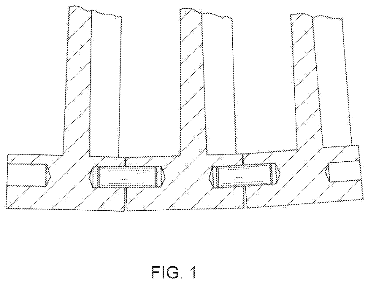
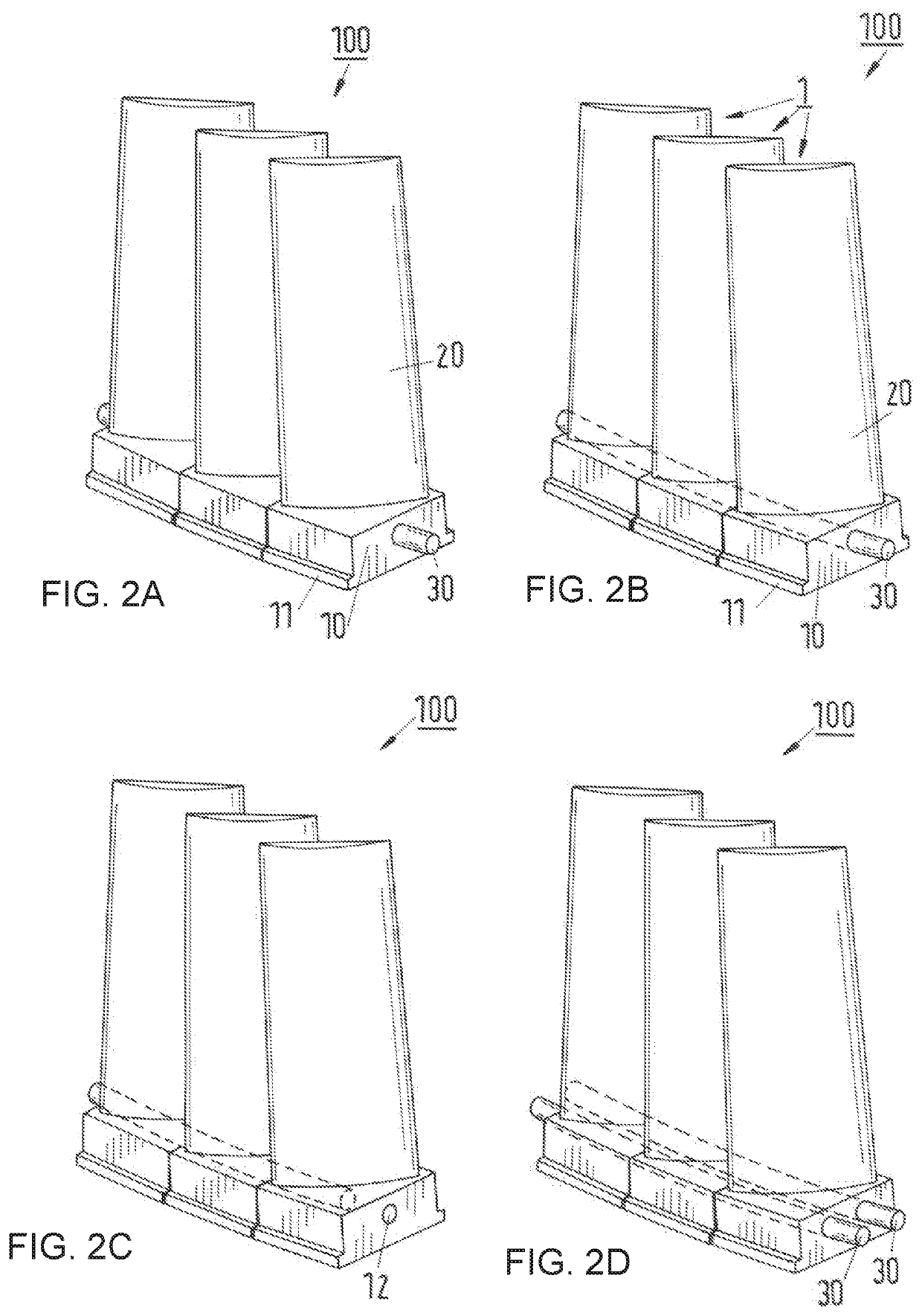
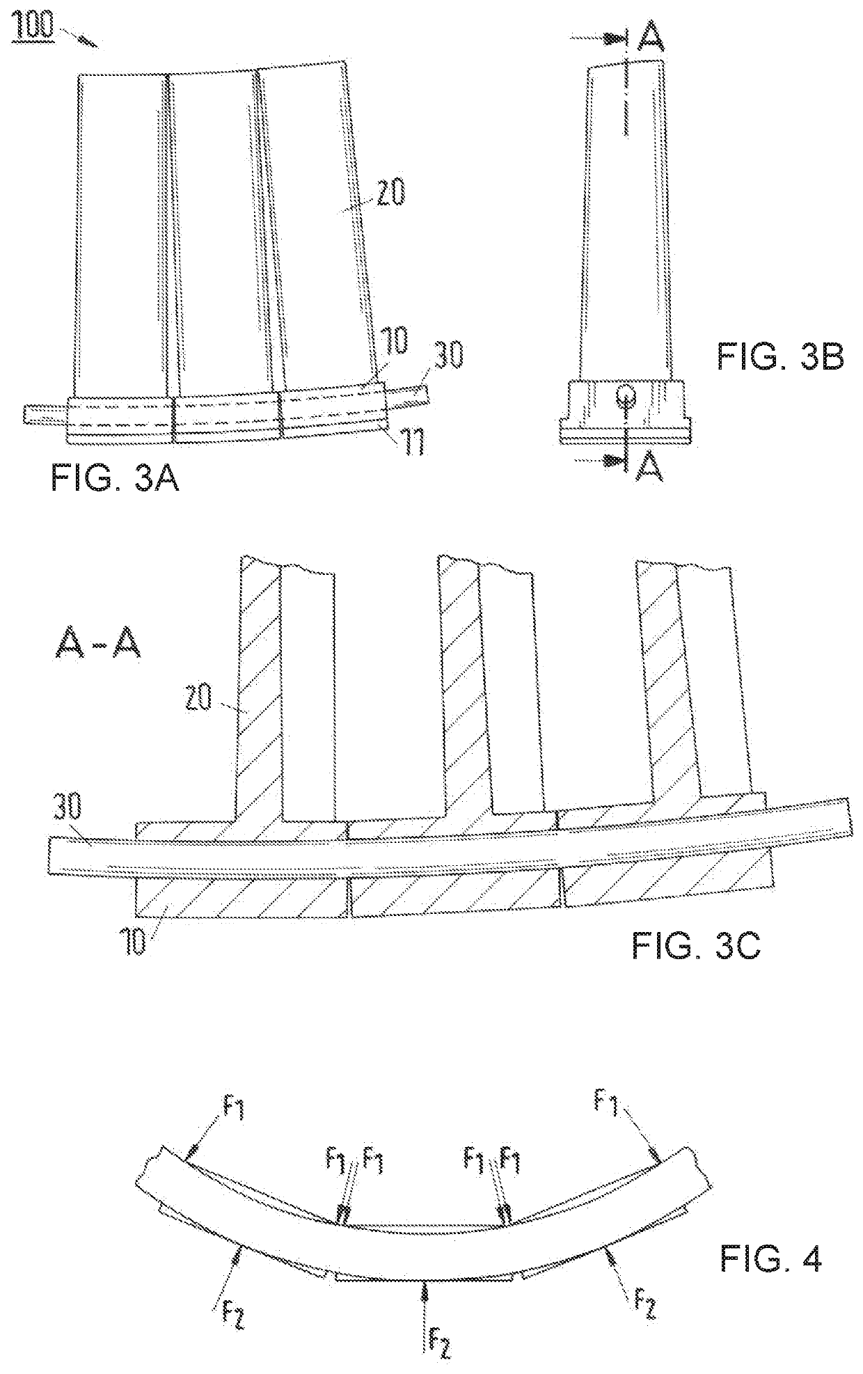
[0026]Those skilled in the art will appreciate that elements in the drawings are illustrated for simplicity and clarity and have not necessarily been drawn to scale. For example, the dimensions of some of the elements in the drawings may be exaggerated relative to other elements to help improve understanding of the various embodiments of the invention. Furthermore, the terms “first”, “second”, and the like herein, if any, are used inter alia for distinguishing between similar elements and not necessarily for describing a sequential or chronological order. Moreover, the terms “front”, “back”, “top”, “bottom”, “up”, “down”, “over”, “under”, “proximal”, “distal”, and the like in the description and / or in the claims, if any, are generally employed for descriptive purposes and not necessarily for comprehensively describing exclusive relative position. Also, the term “engagement feature” may also constitute a “disengagement feature”. Skilled artisans will therefore understand that any of ...


PUM


Abstract

A vane assembly includes a plurality of vane units and a connecting part. Each vane unit includes a base having a through-hole positioned between opposing longitudinal faces of the base. The connecting part includes a lacing bar that is insertable into and through the through-holes for coupling at least two adjacent vane units into the vane assembly. In the vane assembly the connecting part is arranged through the through holes of the plurality of vane units clamping the vane units on the lacing bar.

Description

CROSS-REFERENCE TO RELATED APPLICATION[0001]This application is a U.S. National Stage application of International Application No. PCT / EP2018 / 075018, filed Sep. 17, 2018, which claims priority to European Patent Application No. 17192214.9, filed Sep. 20, 2017, the contents of each of which are hereby incorporated herein by reference.BACKGROUNDField of the Invention[0002]The invention relates to compressor stator vane units and a method of assembling vane units in a casing of the compressor.Background Information[0003]A conventional compressor stator vane unit can include a base for engaging a (semi-circle) slot in a compressor casing and an airfoil extending from the base for cooperating with airfoils of blade units on the compressor rotor. Engagement of the vane unit with the casing slot conventionally is achieved through protrusions extending from transversal faces of the base which cooperate with longitudinal grooves in side walls of the slot. A plurality of vane units may be sli...

Claims


Application Information

Patent Timeline
IPC IPC(8): F01D5/24F01D25/24F01D9/04
CPCF05D2260/36F01D25/246F05D2260/96F01D5/24F01D9/042F05D2260/30
Inventor MATTHEIJ, JOZEF H.G.ALTHUIZEN, TWAN ANTONIUS MARTINUS
Owner SULZER TURBO SERVICES VENLO
Why Eureka
Try Eureka