Capillary assembly useful as connecting capillary

a capillary and assembly technology, applied in the field of capillary assembly, can solve the problems of affecting the robust use of nano-flow lc at ultra high pressure, the thin wall thickness is too fragile for normal use and handling, and the limiting element of the solvent tubing, etc., to achieve the effect of flexible and robust capillary assembly, and facilitate the use of fragile column materials

Inactive Publication Date: 2014-04-24
PROXEON BIOSYST APS
View PDF6 Cites 0 Cited by
  • Summary
  • Abstract
  • Description
  • Claims
  • Application Information

AI Technical Summary

Benefits of technology

[0015]The present invention solves the above problems by providing a means to facilitate the use of fragile column materials. This involves reinforcing the fragile tubing by the addition of steel or PEEK sleeves and / or embedding the fragile tubing in an injection-molded resin such that the fragile tubing is not exposed directly to operator handling and manipulation. Further functional improvement is obtained by including additional components inside the resin. Thereby a versatile and robust capillary assembly is achieved.
[0016]As mentioned above, the capillary assembly according to the present invention makes use of sleeves, preferably steel or PEEK-sleeves, provided only in the end regions of the capillary. In the regions of the capillary where there are no sleeves the capillary is coated by a flexible plasticlayer, which is in direct contact with the capillary. In that way an additional protection against scratches is achieved.

Problems solved by technology

While these components can be made with due care and consideration from present materials, the currently most limiting element has been the tubing that carries the solvent at pressures above 5,000.
The inner diameters tend to range from 5 μm to 300 μm, but any size combination of 360 μm OD and more than 200 μm ID will have very thin wall thickness and will be too fragile for normal use and handling.
Unfortunately, whether materials are used separately or mixed, each existing type of tubing on the market has severe disadvantages that hinder their robust use in nano-flow LC at ultra high pressures.
However, PEEKsil cannot be manufactured with inner diameters below 25 μm and it seems that the inner diameter of PEEKsil in general exhibits rather significant variation over a length of tubing.
This uneven size leads to vastly higher flow restriction than a tube of uniform inner diameter would have and also the risk of blockage caused by particulate matter in the mobile phase of the LC will increase several fold.
A further complication from the use of PEEKsil, is that the inner glass lining may break and fall off in little flakes at and next to the locations where ferrules are tightened in unions and fittings.
Such flakes may subsequently block the flow stream through the tube or damage valves and other active components by scratching their surfaces.
There are many ferrules on the market designed to overcome this problem of damaging the tubing ends, but none have entirely solved the problem.Stainless steel is extremely robust in terms of pressures it will withstand, and it is usually straightforward to obtain leak-proof connections to unions and other fittings, using a wide variety of ferrules and nuts.
However, steel tubing cannot be made with an inner diameter below 125 μm and usually the lower limit is in fact 250 μm when the OD is one of the two standards of 1 / 32″ or 1 / 16″.
If one needs more narrow ID tubing then the OD must be reduced as well, upon which the tubing becomes fragile.
Another complication of using steel tubing is that acidified aqueous buffers tend to cause corrosion and salt formation in steel tubing.
And an additional complication is that some analytes, e.g. phospho-peptides tend to react with iron-ions of the steel surface and adsorb, disintegrate, or otherwise disappear from the sample.Stainless steel tubing can be made with glass lining (e.g. catalog number 24951 from www.SigmaAldrich.com) which alleviates the chemical reactivity issues of steel but this tubing cannot be obtained with an inner diameter below 250 μm.Fused silica glass tubing for chromatography purposes is made of glass where the outside is coated by a layer of poly-imide that has a thickness usually between 8 μm and 20 μm.
Fused silica tubing without the polymer coating is extremely fragile and breaks even with careful handling and when exposed to only moderate pressure; hence it has no useful application as high pressure flow lines.
This is however only true of tubing where the coating is absolutely intact and it is a frequent observation that even slight scratches in the poly-imide coating will cause fracture of the fused silica tubing even at moderate pressures or strains.
Therefore, whereas multiple types of tubing for capillary and nano-flow chromatography exists, none of the existing materials or material combinations presents satisfactory solutions in terms of mechanical and physical robustness, chemical inertness, or selection of inner diameter.

Method used


Image

  • Capillary assembly useful as connecting capillary
  • Capillary assembly useful as connecting capillary
  • Capillary assembly useful as connecting capillary

Examples


Embodiment Construction

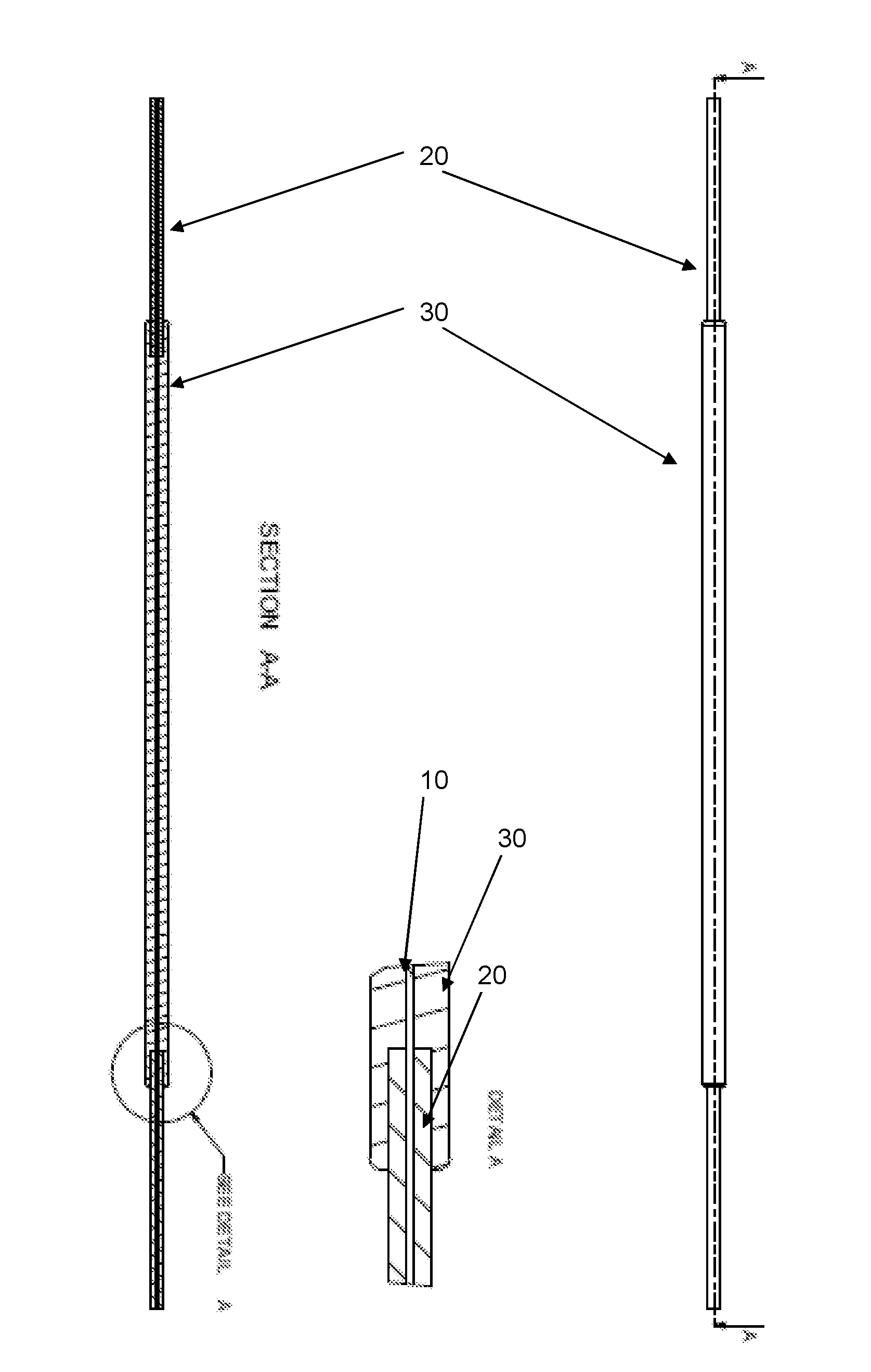
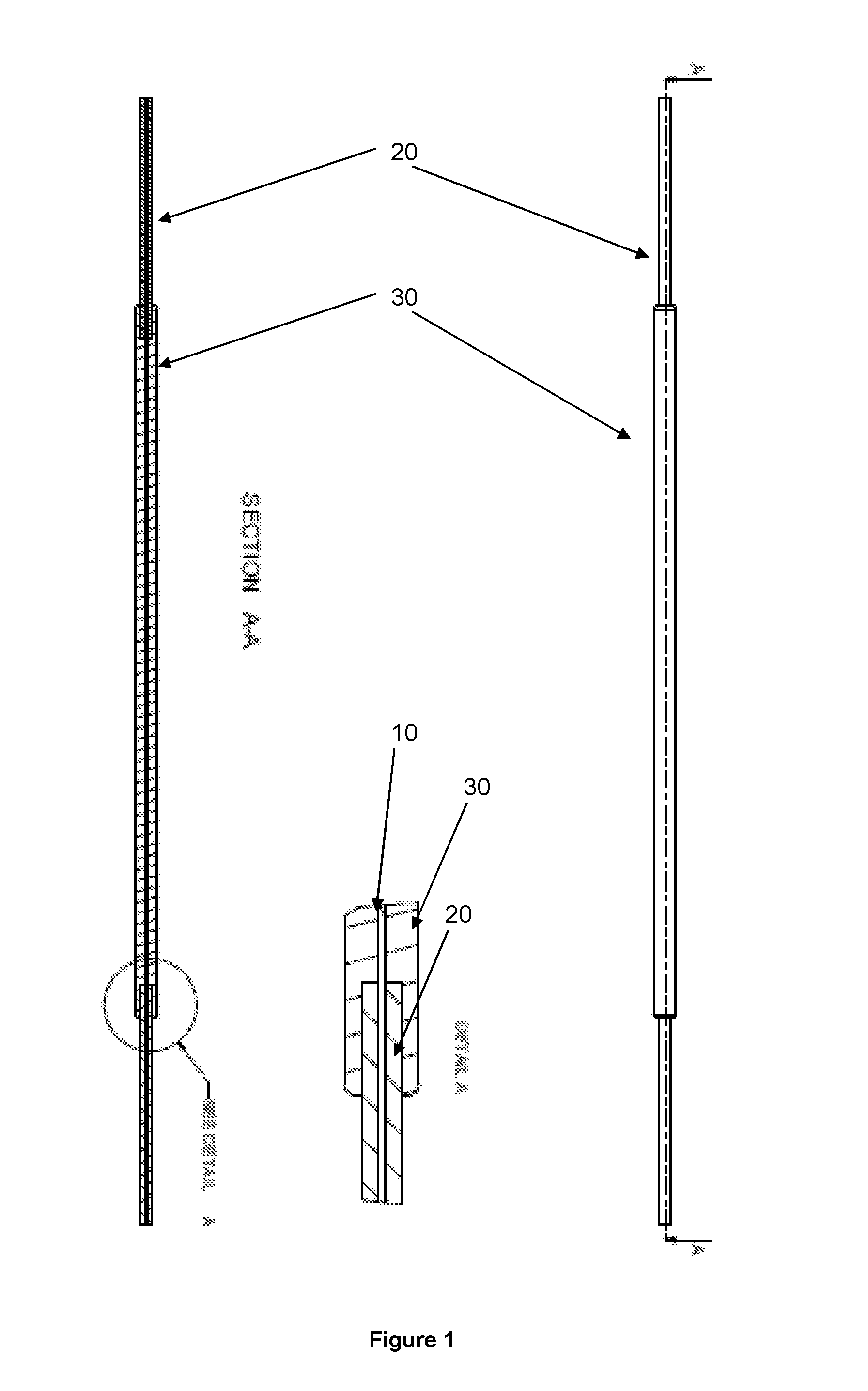
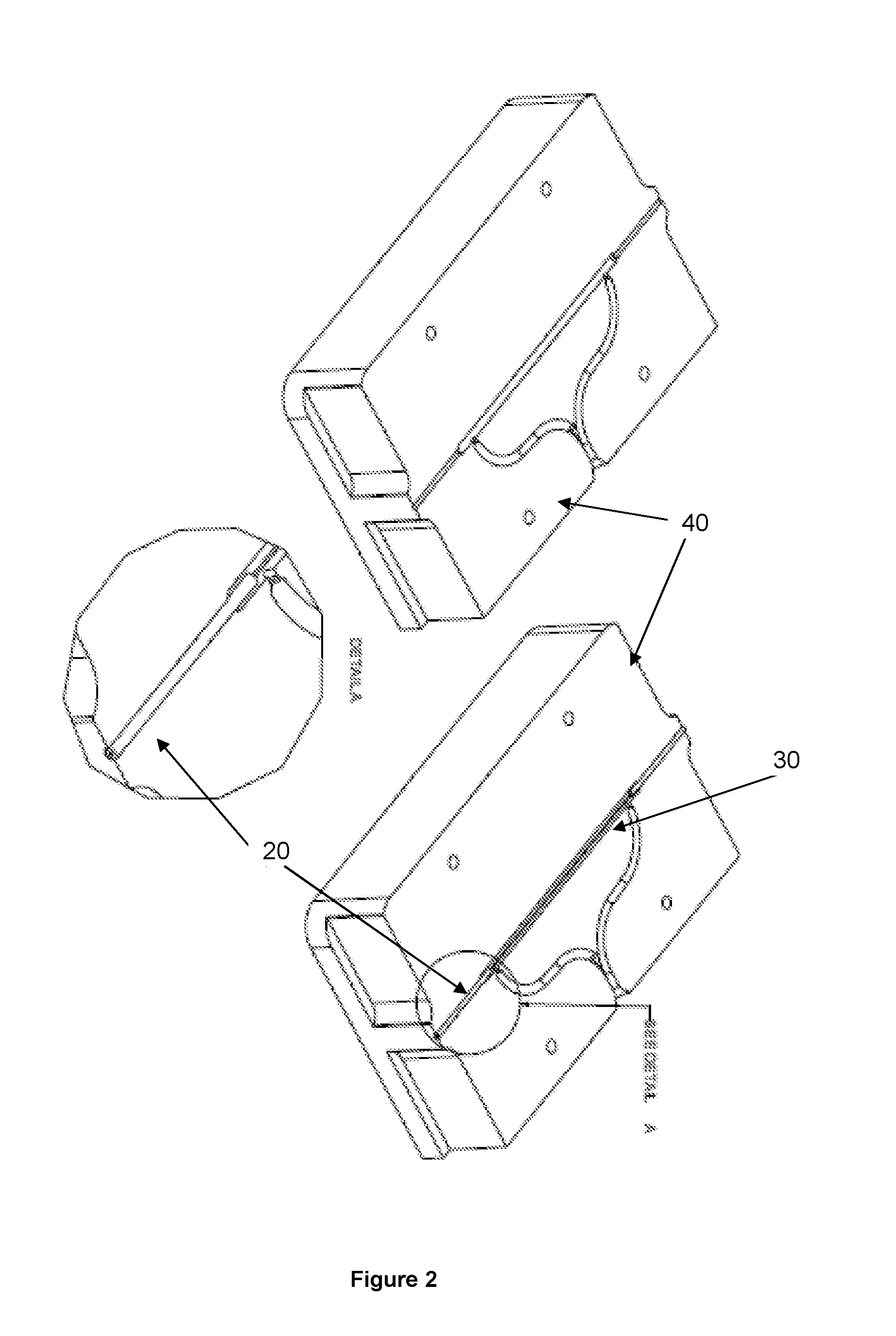
[0040]The arrangement as shown in FIGS. 1 and 2 comprises a silica capillary with sleeves. The molding material comprises a plastic material, for example, a thermoplastic material, such as polyamide and polyurethane based MacroMelt™. The plastic material is chosen for being formed with a forming tool comprising a mold. In some embodiments, the plastic material can be melted completely and afterwards cooled down to ambient temperature. Therefore, the plastic material can realize a chemical bond with the outer surfaces of the capillary and sleeves.

[0041]Specifically FIG. 1 shows a fused silica capillary (10) ˜360 μm OD with PEEK or steel sleeves (20) at each end and resin (30) that covers the central part of the capillary (10) including approximately one third of the central end of each sleeve (20). Detail A of FIG. 1 shows the overlap of resin onto the sleeve. Regardless of the material used for the sleeve, typical sleeve dimensions would be an inner diameter of ˜375 μm, length of ap...


PUM

PropertyMeasurementUnit
diametersaaaaaaaaaa
inner diametersaaaaaaaaaa

Abstract

There is provided a capillary assembly suitable for connecting various components of an analytical measuring device, for example a liquid chromatograph or a capillary electrophoresis device, to each other. Specifically, this involves reinforcing the fragile tubing by the addition of PEEK or steel sleeves and / or embedding the tubing in an injection-molded resin such that the tubing is not exposed directly to operator handling and manipulation. Further functional improvement is obtained by including additional components inside the resin. Thereby a versatile and robust capillary assembly is achieved.

Description

FIELD OF THE INVENTION[0001]The present invention relates to a capillary assembly suitable for connecting various components of an analytical measuring device, for example a liquid chromatograph or a capillary electrophoresis device, to each other.BACKGROUND OF THE INVENTION[0002]In a liquid chromatographic (LC) system, connecting capillaries, as well as columns made from capillaries, are often used.[0003]In a liquid chromatographic system, the LC column is located between an injector and an LC detector to separate one or more constituents of interest from the various interferences in a sample to permit detection of these constituents of interest by an LC detector.[0004]Capillary LC is a micro-version of traditional liquid chromatography and its popularity has grown rapidly during the past decades. Capillary LC columns have extremely low solvent consumption and require low volumes of samples for analysis. NanoLC is the name given to further miniaturization of chromatography, where f...

Claims


Application Information

Patent Timeline
Patent Type & Authority Applications(United States)
IPC IPC(8): B01D15/22G01N30/60B29D23/00
CPCB01D15/22G01N30/60B29D23/00G01N30/6004G01N30/6039G01N2030/3061G01N2030/6013
Inventor VORM, OLE
Owner PROXEON BIOSYST APS
Why Eureka
Try Eureka