Magnetic inductor electric motor and manufacturing method therefor

a technology of magnetic inductor and electric motor, which is applied in the direction of manufacturing stator/rotor body, magnetic circuit rotating parts, and shape/form/construction of magnetic circuits, etc., can solve problems such as magnet holding strength, and achieve the effect of high space factor and increased output without increasing axial dimensions of electric motors

Active Publication Date: 2016-08-25
MITSUBISHI ELECTRIC CORP
View PDF10 Cites 8 Cited by
  • Summary
  • Abstract
  • Description
  • Claims
  • Application Information

AI Technical Summary

Benefits of technology

[0012]According to the present invention, because the concentrated winding coils are wound into concentrated windings, and the magnet blocks have flange portions that protrude on two circumferential sides from radially inner end portions of shaft portions, output can be increased without increasing axial dimensions of the electric motor. Because the teeth of the core blocks are produced into a tapered shape, and the core blocks do not have flange portions that protrude on two circumferential sides from the radially inner end portions of the teeth, the concentrated winding coils can be mounted to the pairs of teeth so as to have a high space factor.

Problems solved by technology

However, in electric motors that are used in “electrically assisted turbochargers” in which the electric motor is disposed between a turbine and a compressor of an automotive supercharger, since high-speed rotation that exceeds 100,000 revolutions per minute is required, problems with magnet holding strength arise if conventional permanent magnet electric motors are used in these electric motors.

Method used


Image

  • Magnetic inductor electric motor and manufacturing method therefor
  • Magnetic inductor electric motor and manufacturing method therefor
  • Magnetic inductor electric motor and manufacturing method therefor

Examples


embodiment 1

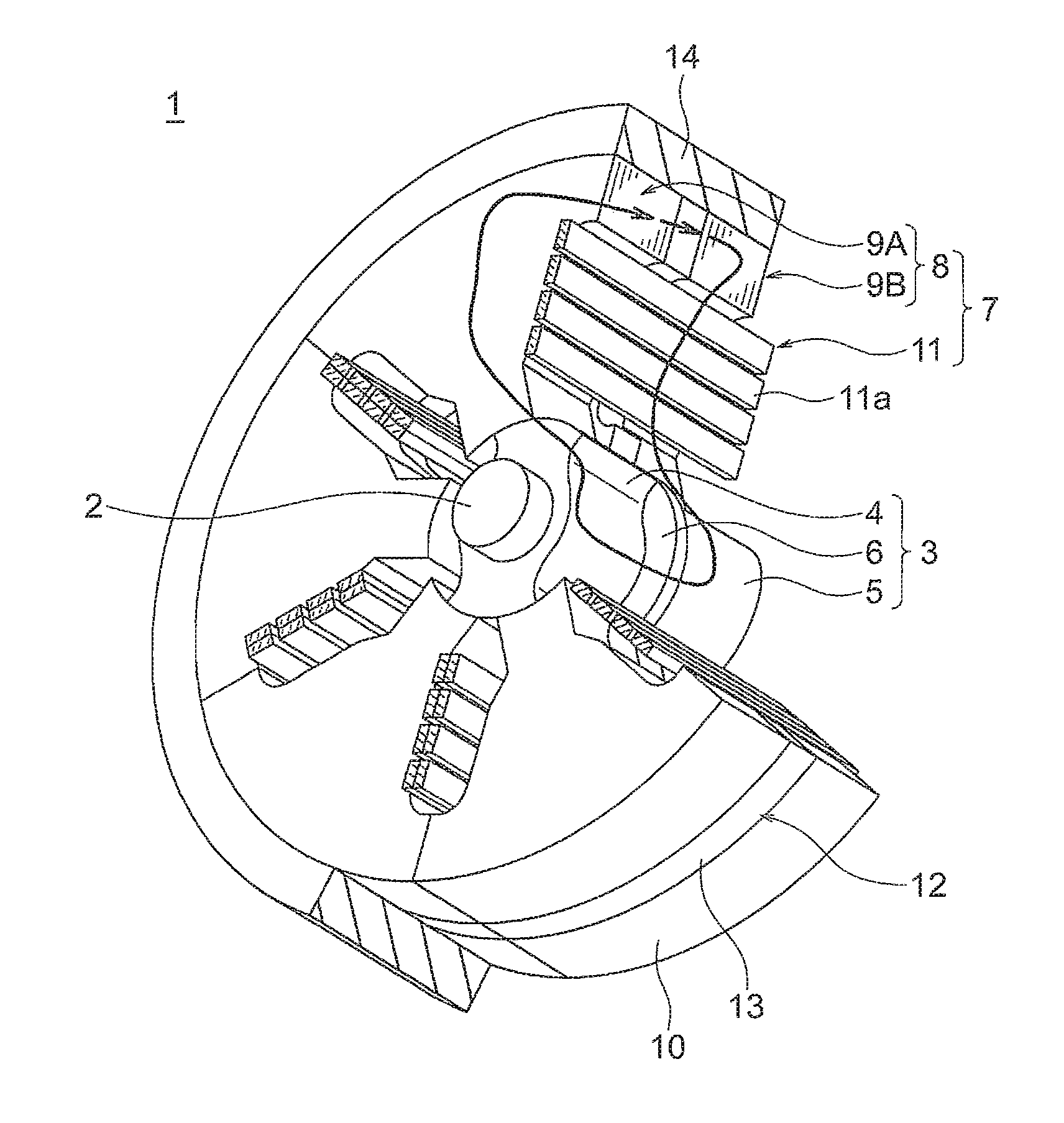
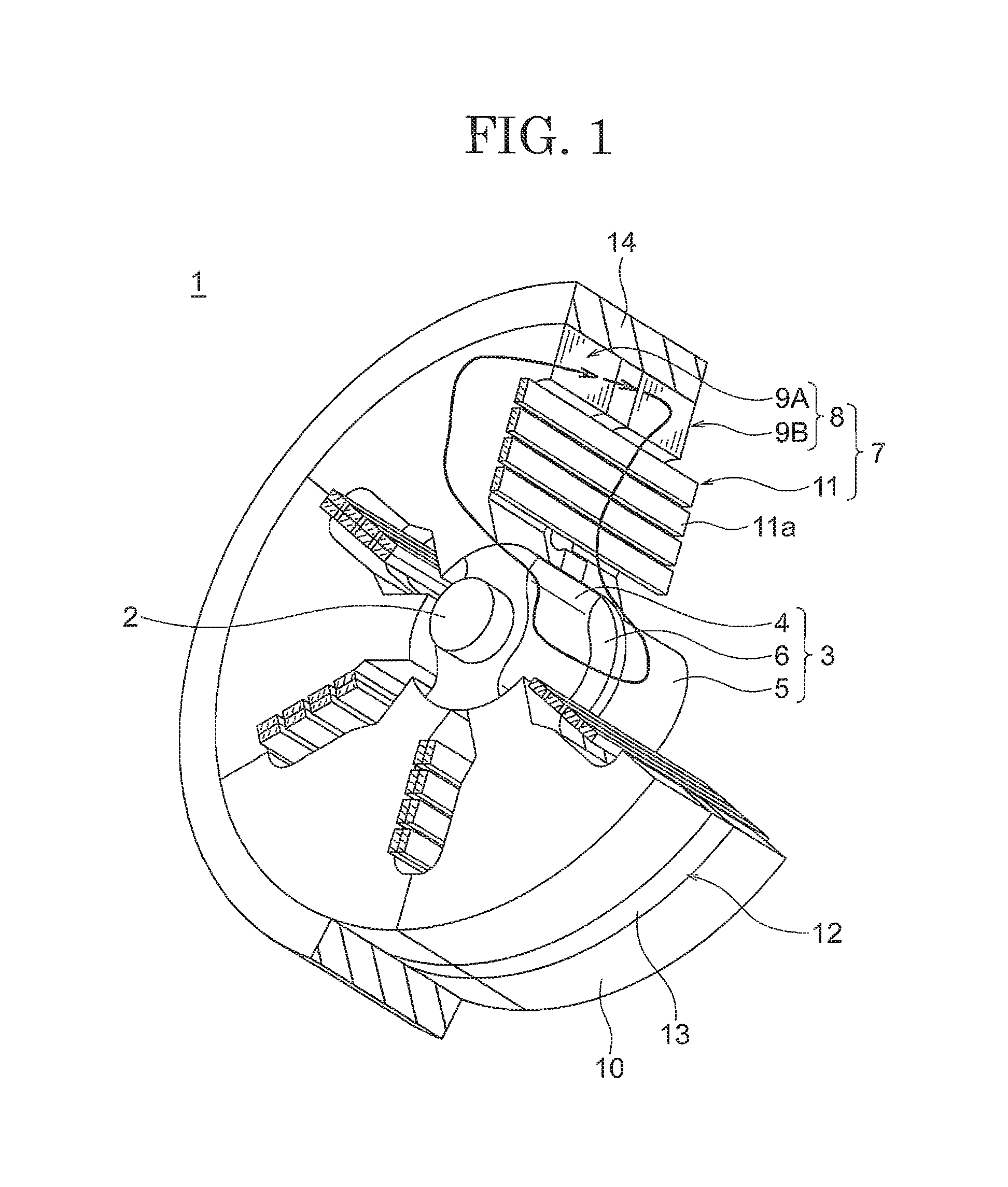
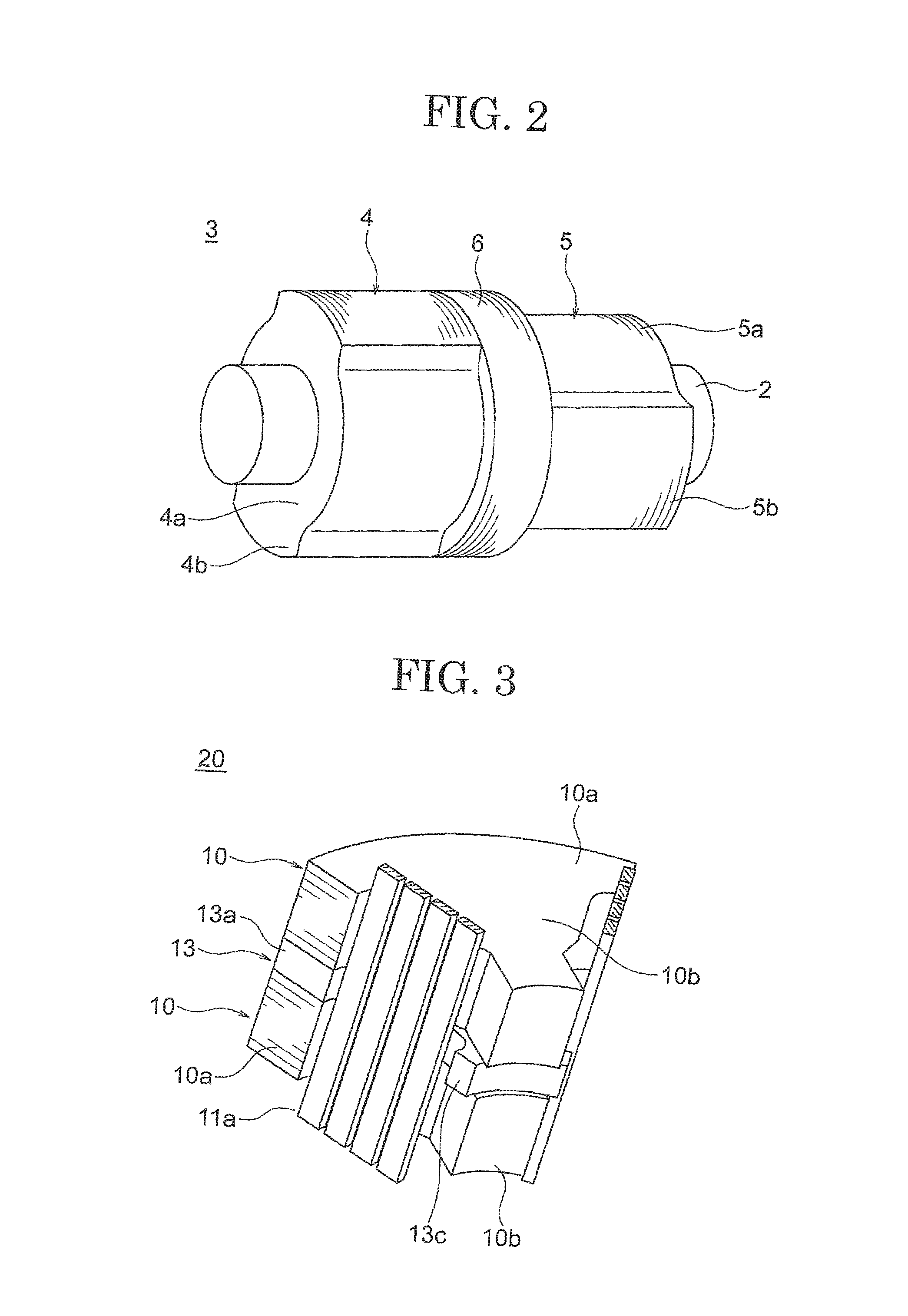
[0033]FIG. 1 is a partially cut away oblique projection that shows an overall configuration of a magnetic inductor electric motor according to Embodiment 1 of the present invention, FIG. 2 is an oblique projection that shows a rotor in the magnetic inductor electric motor according to Embodiment 1 of the present invention, FIG. 3 is a partially cut away oblique projection that shows a stator assembly in the magnetic inductor electric motor according to Embodiment 1 of the present invention, FIG. 4 is an oblique projection that shows a core block in the magnetic inductor electric motor according to Embodiment 1 of the present invention, and FIG. 5 is an oblique projection that shows a magnet block in the magnetic inductor electric motor according to Embodiment 1 of the present invention. Moreover, for simplicity, portions of concentrated winding coils and insulators have been omitted from FIGS. 1 and 3.

[0034]In FIG. 1, a magnetic inductor electric motor 1 includes: a rotor 3 that is ...

embodiment 2

[0072]FIG. 13 shows a diagram that explains a configuration of a stator assembly in a magnetic inductor electric motor according to Embodiment 2 of the present invention, FIG. 13A being a plan when viewed from radially inside, and FIG. 13B being an oblique projection.

[0073]In FIG. 13, a magnet block 13A is formed such that an axial thickness of flange portions 13d that protrude on two circumferential sides from a radially inner end portion of a shaft portion 13b is thicker than an axial thickness of the shaft portion 13b.

[0074]Moreover, the rest of the configuration is formed in a similar or identical manner to that of Embodiment 1 above.

[0075]In Embodiment 2, the volume of the magnet block 13A is increased compared to Embodiment 1 above because the axial thickness of the flange portions 13d is thicker. Thus, the amount of magnetic flux that is induced in the salient poles 4b and 5b of the first and second rotor cores 4 and 5 is increased, further increasing the rotational driving ...

embodiment 3

[0076]FIG. 14 is an oblique projection that shows a stator assembly in a magnetic inductor electric motor according to Embodiment 3 of the present invention.

[0077]In FIG. 14, a magnet block 13B is formed such that an expanded portion 13e that has an axial thickness that is similar or identical to that of a pair of flange portions 13d links the flange portions 13d by increasing a thickness of a radially inner end portion of a shaft portion 13b. Recess portions 10d into which the expanded portion 13e is fitted are recessed into radially inner end portions of surfaces of teeth 10b of core blocks 10A that face the magnet block 13B.

[0078]Moreover, the rest of the configuration is formed in a similar or identical manner to that of Embodiment 2 above.

[0079]In Embodiment 3, because an expanded portion 13e that has an axial thickness that is similar or identical to that of a pair of flange portions 13d is formed on a radially inner end portion of a base portion 13b so as to link between the ...


PUM


Abstract

A first stator core and a second stator ore are configured by arranging core block pairs into an annular shape, the core block pairs being configured by stacking together core blocks so as to be spaced apart axially, each of the core blocks including a core back portion and one tooth, and a permanent magnet is configured so as to be divided into a plurality of magnet blocks that each include: a base portion; one shaft portion that protrudes radially inward from an inner circumferential surface of the base portion; and flange portions that protrude on two circumferential sides from a radially inner end portion of the shaft portion, the magnet blocks being held between the core block pairs such that the base portion and the shaft portion are positioned inside the core block pairs and such that the flange portions protrude circumferentially from the core block pairs.

Description

TECHNICAL FIELD[0001]The present invention relates to a magnetic inductor electric motor that is used in applications such as electrically assisted turbochargers that are driven in a high-speed rotational region, and to a manufacturing method therefor.BACKGROUND ART[0002]Permanent-magnet synchronous electric motors in which a permanent magnet that functions as a magnetic field means is mounted to a rotor are known conventionally. However, in electric motors that are used in “electrically assisted turbochargers” in which the electric motor is disposed between a turbine and a compressor of an automotive supercharger, since high-speed rotation that exceeds 100,000 revolutions per minute is required, problems with magnet holding strength arise if conventional permanent magnet electric motors are used in these electric motors.[0003]In consideration of these conditions, conventional magnetic inductor electric motors have been proposed in which a permanent magnet that functions as a magnet...

Claims


Application Information

Patent Timeline
Patent Type & Authority Applications(United States)
IPC IPC(8): H02K21/26H02K1/24H02K15/04H02K15/02H02K15/03H02K1/17H02K3/18
CPCH02K21/44H02K1/17H02K1/24H02K21/26H02K15/022H02K15/03H02K15/04H02K3/18
Inventor OGAWA, TORUARITA, HIDEAKIDAIKOKU, AKIHIROKOMATSU, TAIGAMIYAMA, YOSHIHIRO
Owner MITSUBISHI ELECTRIC CORP
Why Eureka
Try Eureka