Transceiver configuration for millimeter wave wireless communications

a wireless communication and transmission device technology, applied in the field of wireless communication systems, can solve the problems of increasing hardware components, affecting the operation of the transmission device, and increasing the hardware footprint, so as to reduce the hardware footprin

Active Publication Date: 2016-08-25
QUALCOMM INC
View PDF11 Cites 56 Cited by
  • Summary
  • Abstract
  • Description
  • Claims
  • Application Information

AI Technical Summary

Benefits of technology

[0010]The described features generally relate to one or more improved systems, methods, and / or devices for transceiver architecture in a millimeter wave wireless communication system. Generally, the described transceiver architecture may provide two transceivers positioned on separate chip modules and connected using a single coaxial cable. The two transceivers may share a baseband sub-module to reduce the hardware footprint. In some examples, a first transceiver chip module may include the baseband sub-module and the first RFFE circuitry and associated antenna array. A second transceiver chip module may include a second RFFE circuitry and associated antenna array. The second transceiver chip module may be located separate from the first transceiver chip module, but connected to the baseband sub-module via a coaxial cable. The first transceiver chip module may have a ZIF transceiver architecture and the second chip module may have a SIF transceiver architecture.

Problems solved by technology

Current configurations, therefore, utilize separate circuitry, modules, and circuit boards for each transceiver configuration which results in added hardware components, excessive hardware footprints, and associated power requirements.
Current configurations, therefore, utilize separate circuitry, modules, and circuit boards for each transceiver configuration which results in added hardware components, an excessive hardware footprint, and associated power requirements.
A system design that does not take into account the increased throughput available at short distances may have a reduced throughput limit.

Method used


Image

  • Transceiver configuration for millimeter wave wireless communications
  • Transceiver configuration for millimeter wave wireless communications
  • Transceiver configuration for millimeter wave wireless communications

Examples


Embodiment Construction

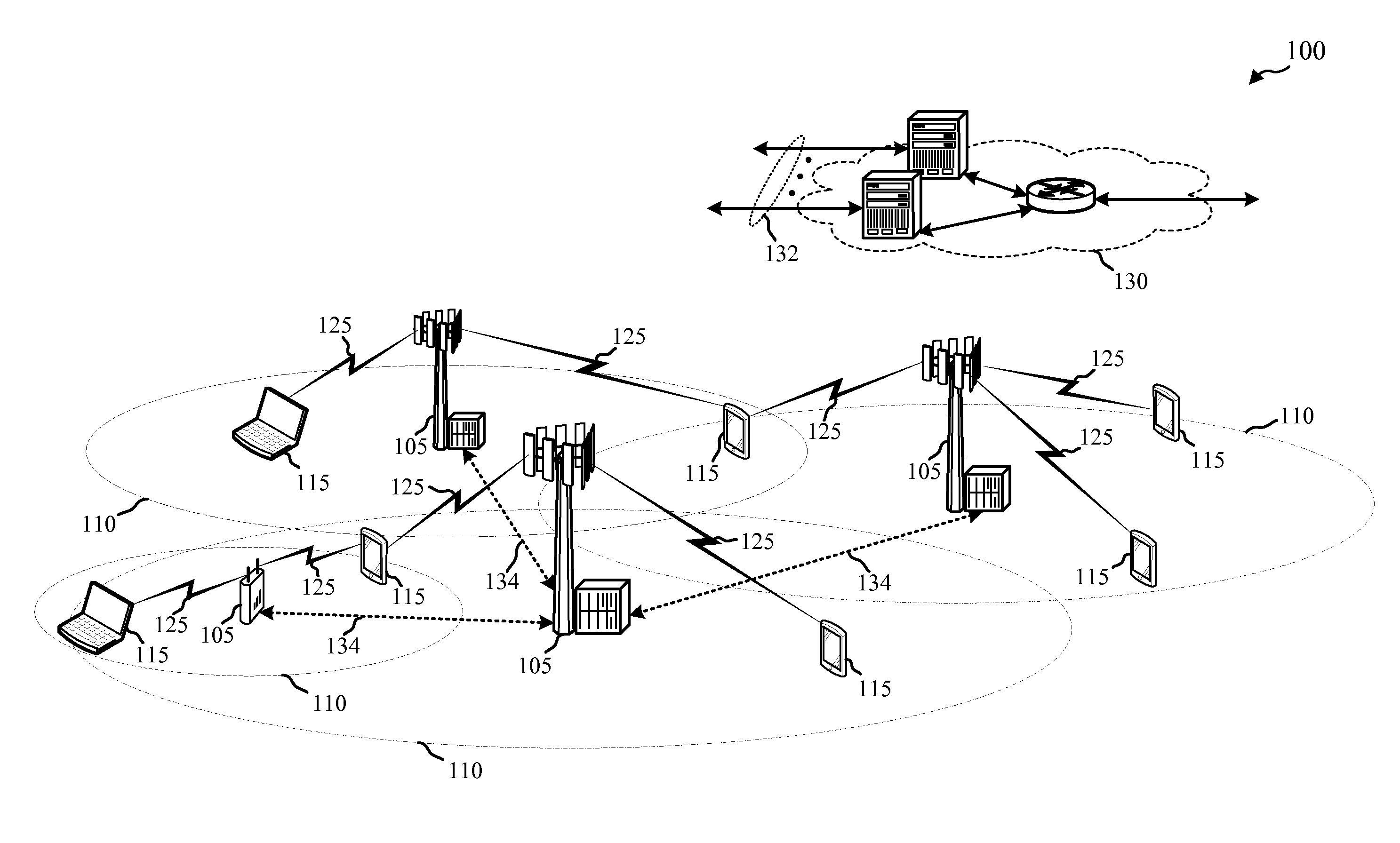
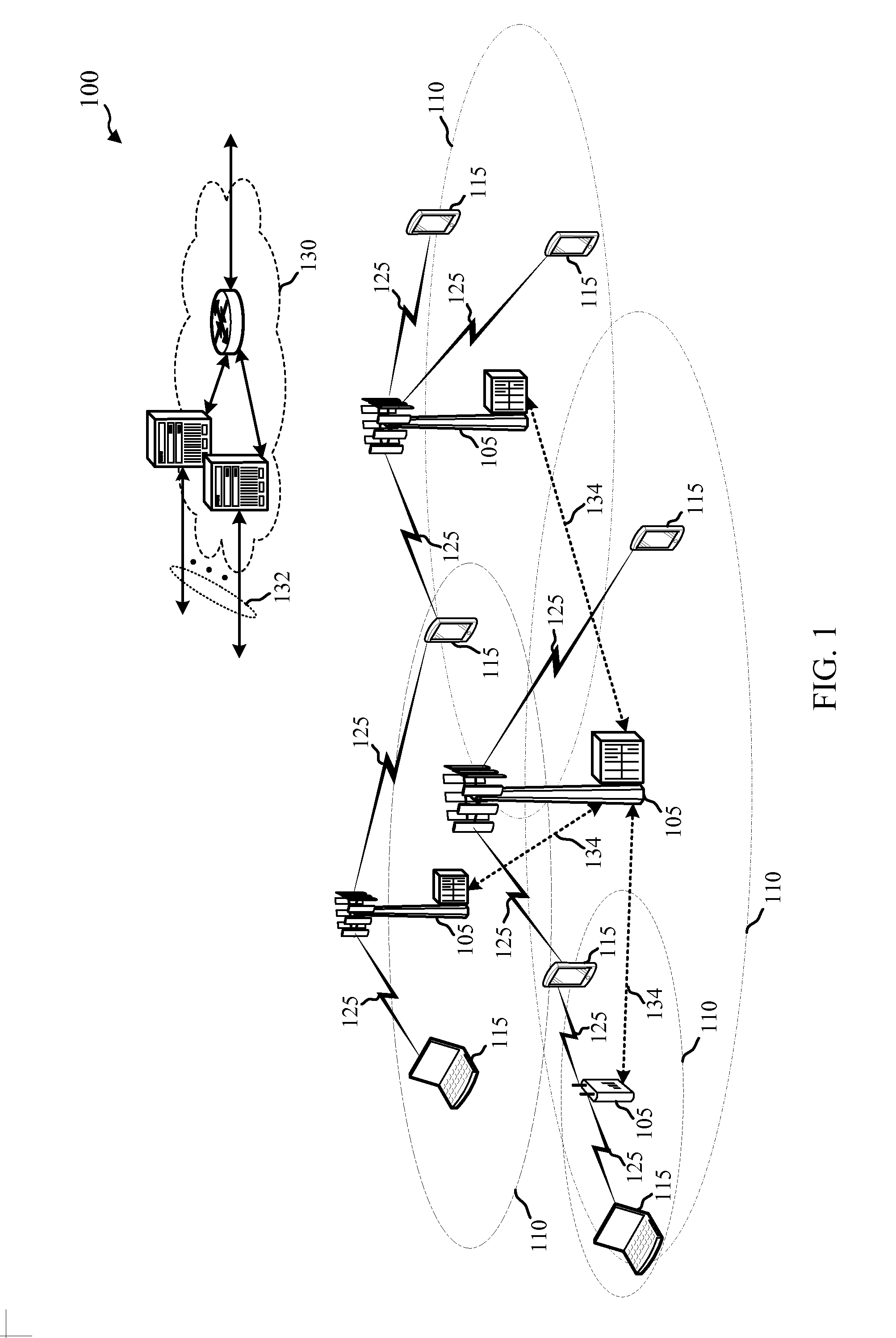
[0078]Evolving wireless communication systems may communicate using one or more of several mmW frequency ranges, e.g., 28 GHz, 40 GHz, 60 GHz, etc. Different mmW frequency ranges may be used for different communication systems protocols, e.g., Wi-Fi communication systems, telecommunication systems, etc. Communications using such mmW frequencies, however, introduce design difficulties from an operational perspective (e.g., limited propagation distance) as well as from a hardware perspective. For example, processing signals in the mmW frequency range requires careful consideration and selection of components, component / module spacing limitations, etc., in order to reduce signal loss. Other considerations include spacing and positioning of antenna arrays for each frequency range in a device that has limited available space and that avoids interference caused by the user, e.g., how a user may typically hold the device.

[0079]Millimeter wave systems may be used for a variety of functions,...


PUM


Abstract

Methods, systems, and devices are described for transceiver architecture for millimeter wave wireless communications. A device may include two transceiver chip modules configured to communicate in different frequency ranges. The first transceiver chip module may include a baseband sub-module, a first radio frequency front end (RFFE) component and associated antenna array. The second transceiver chip module may include a second RFFE component and associated antenna array. The second transceiver chip module may be separate from the first transceiver chip module. The second transceiver chip module may be electrically coupled to the baseband sub-module of the first transceiver chip module.

Description

CROSS REFERENCES[0001]The present application for patent claims priority to U.S. Provisional Patent Application No. 62 / 119,764 by Weissman et al., entitled “Transceiver Configuration for Millimeter Wave Wireless Communications,” filed Feb. 23, 2015, U.S. Provisional Patent Application No. 62 / 119,766 by Weissman et al., entitled “Transceiver Architecture for Millimeter Wave Wireless Communications,” filed Feb. 23, 2015, and U.S. Provisional Patent Application No. 62 / 120,815 by Weissman et al., entitled “Multiple Array MMW Transceiver Operation,” filed Feb. 25, 2015 assigned to the assignee hereof, and expressly incorporated by reference herein.BACKGROUND[0002]1. Field of the Disclosure[0003]The present disclosure relates to wireless communication systems, and more particularly to a transceiver configuration for millimeter wave wireless communications.[0004]2. Description of Related Art[0005]Wireless communication systems are widely deployed to provide various types of communication c...

Claims


Application Information

Patent Timeline
Patent Type & Authority Applications(United States)
IPC IPC(8): H04B1/00H04W72/04
CPCH04W72/0453H04B1/0064H04B1/40H04B1/401H04B7/0695H04B1/26H04B1/30H04W72/542
Inventor WEISSMAN, HAIM MENDELRAVIV, LIORHE, XIAOYINAPARIN, VLADIMIR
Owner QUALCOMM INC
Why Eureka
Try Eureka