
Barrel shifter for a microprocessor

a microprocessor and shifter technology, applied in the direction of coding, memory adressing/allocation/relocation, instruments, etc., can solve the problems of less than ideal solution, complicated hardware design, and increased complexity, so as to reduce the footprint of silicon, improve performance, and reduce power consumption

Inactive Publication Date: 2005-12-29
ARC INT LTD
View PDF22 Cites 11 Cited by
  • Summary
  • Abstract
  • Description
  • Claims
  • Application Information

AI Technical Summary

Benefits of technology

[0014] Thus, there exists a need for a barrel shifter that ameliorates and / or eliminates one or more of the above noted problems. In particular, there exists a need for a barrel shifter with reduced power consumption, improved performance and / or reduction of silicon footprint as compared with conventional barrel shifter devices.
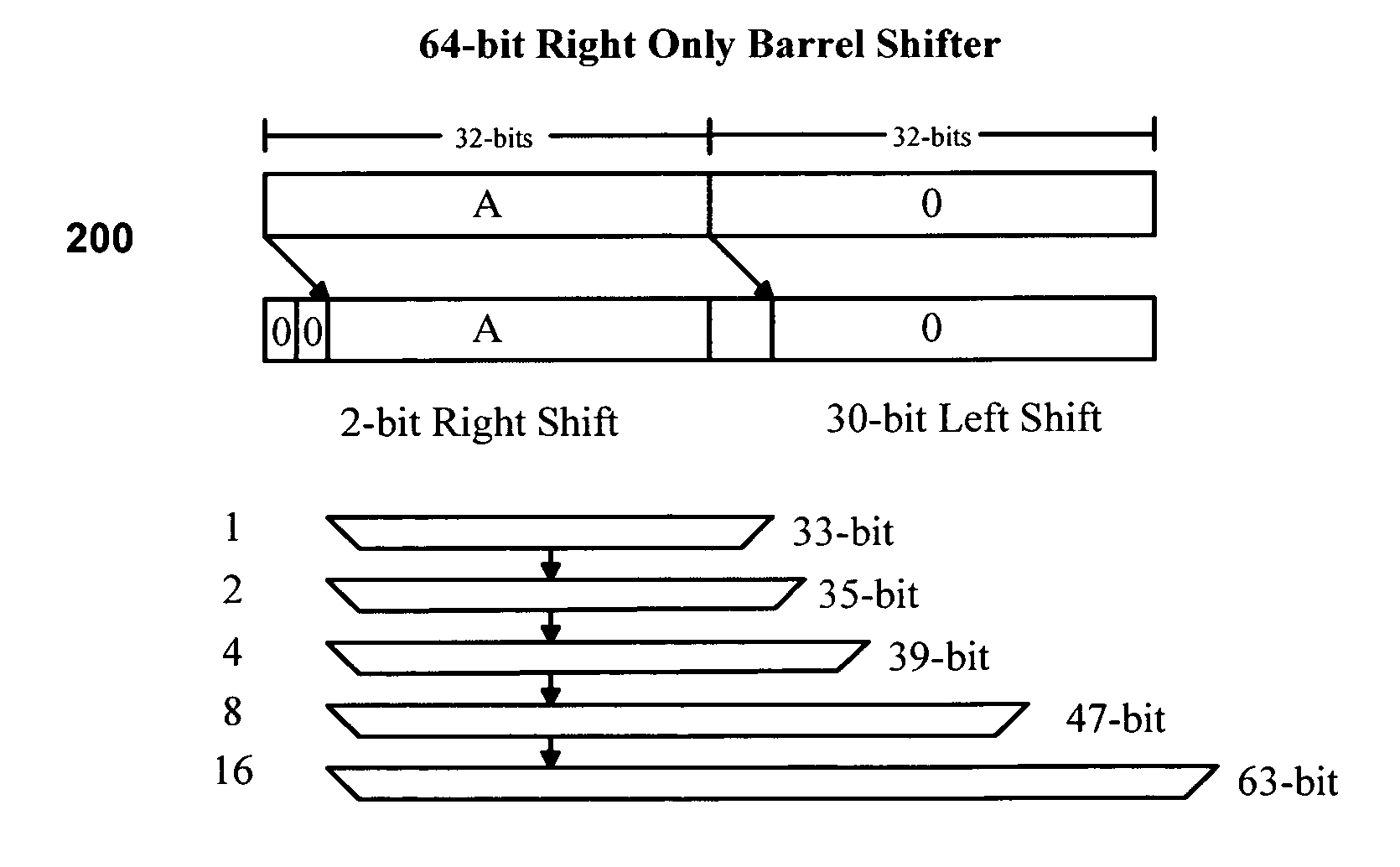
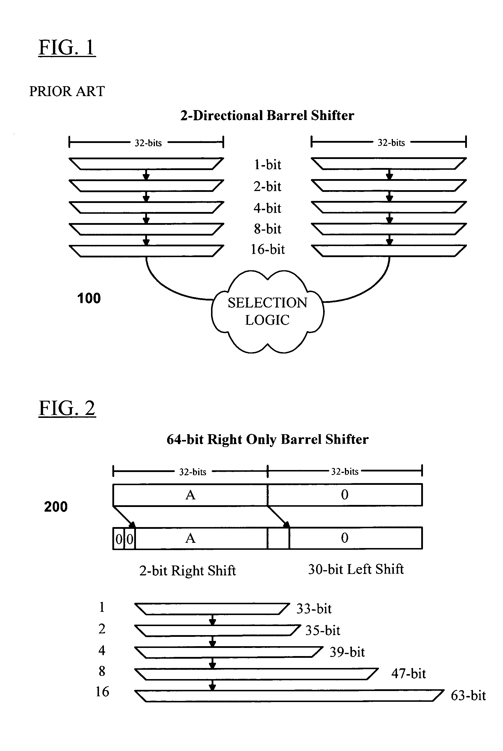
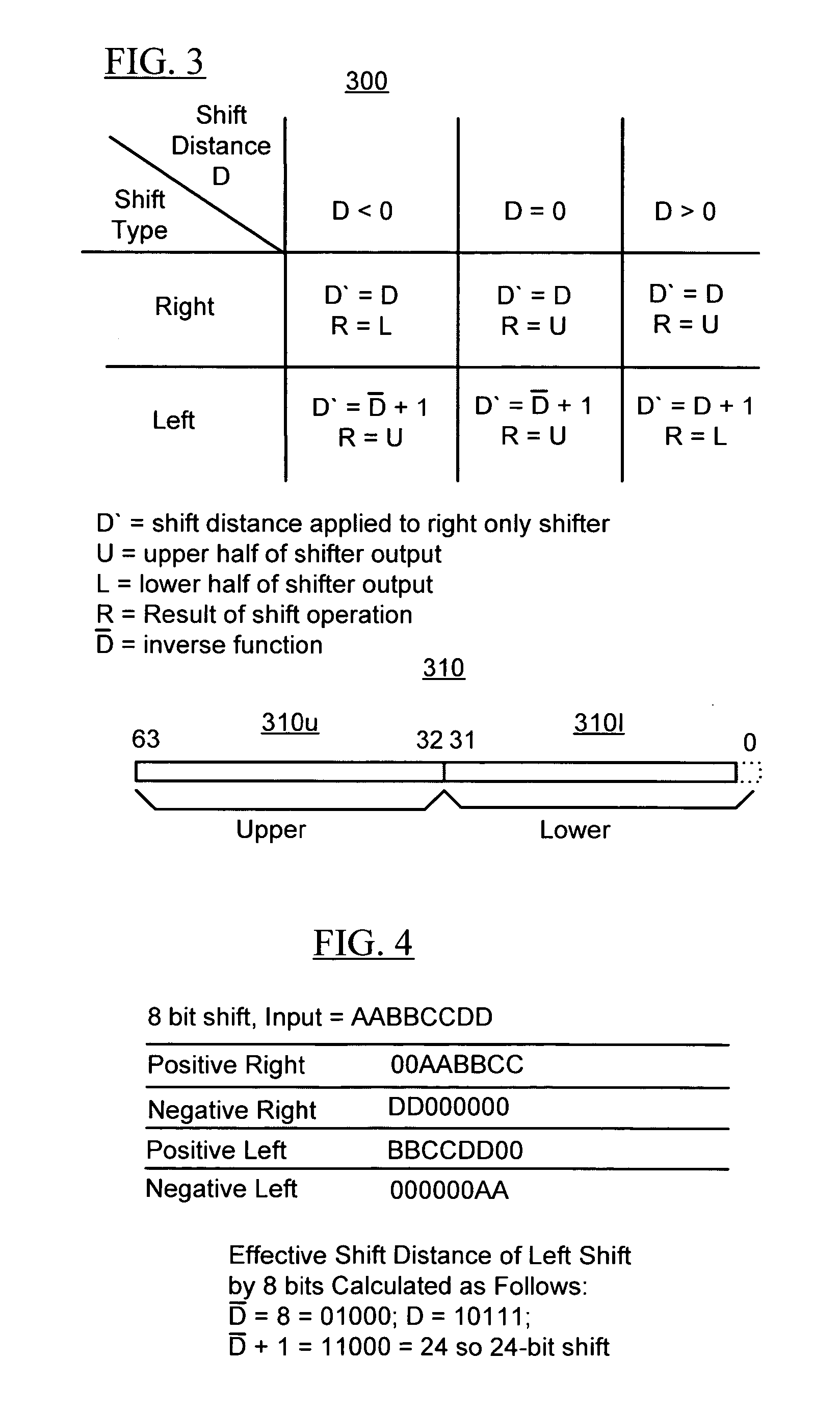
[0015] In various embodiments, this is accomplished through a microprocessor architecture that utilizes a barrel shifter characterized by reduction in complexity, reduced power consumption and enhanced capability over conventional barrel shifter designs. In various exemplary embodiments, the barrel shifter comprises a 64 bit right-shifting barrel shifter capable of right and left directional shifts of a 32 bit input with positive or negative shift distance. In various exemplary embodiments, a right shift of n bits (n<32) is equivalent to a negative left shift of 32-n bits, and a left shift by n bits is equivalent to a negative right shift of 32-n bits. In various exemplary embodiments, the barrel shifter is comprised of a 5 series oriented multiplexers, each shifting by a distance of 1, 2, 4, 8, 16 and 32 bits respectively. The barrel shifter also takes advantage of the fact that all bits between the bit length of the multiplexer stage and the 64th bit are zero. As a result, no hardware is necessary to keep track of these bits. Thus, five series multiplexers having lengths of 33, 35, 39, 47 and 63 bits respectively can be employed having a reduced hardware footprint as compared to five 64-bit multiplexers or dual 32 bit multiplexers as are typically employed. Such a barrel shifter also permits rotation functions with minimal additional hardware logic.

Problems solved by technology

Larger data words, however, require larger digital circuits to manipulate the data, leading to greater cost and complexity.
The conventional barrel shifter is effective at shifting, however, it is a less than ideal solution because the redundant hardware structure occupies extra space on the chip, consumes additional power and complicates the hardware design.

Method used


Image

  • Barrel shifter for a microprocessor
  • Barrel shifter for a microprocessor
  • Barrel shifter for a microprocessor

Examples


Embodiment Construction

[0032] The following description is intended to convey a thorough understanding of the invention by providing specific embodiments and details involving various aspects of a new and useful microprocessor architecture. It is understood, however, that the invention is not limited to these specific embodiments and details, which are exemplary only. It further is understood that one possessing ordinary skill in the art, in light of known systems and methods, would appreciate the use of the invention for its intended purposes and benefits in any number of alternative embodiments, depending upon specific design and other needs.

[0033] Referring now to FIG. 2, an exemplary embodiment of an improved barrel shifter architecture is shown for a microprocessor, wherein a 64-bit right only shifter 200 can provide the same functionality as the conventional double 32-bit shifter 100 shown in FIG. 1, while having a reduced circuit complexity and reduced power consumption. If the 64-bit shifter 200 ...


PUM


Abstract

A 2N bit right only barrel shifter for a microprocessor comprising upper and lower N bit shifter portions. A N bit input is put in the upper portion. An X bit right shift of the N bit number yields the results in the N bit upper portion and the result of an N-X bit left shift in the lower portion. The N bit shifter is comprised of a Log2N stage multiplexer where in each successive stage of the multiplexer adds 2x additional bits where x increments from 0 to (Log2N-1).

Description

CROSS REFERENCE TO RELATED APPLICATION(S) [0001] This application claims priority to provisional application No. 60 / 572,238 filed May 19, 2004, entitled “Microprocessor Architecture,” hereby incorporated by reference in its entirety.FIELD OF THE INVENTION [0002] This invention relates generally to microprocessor architecture and more specifically to a design for a rotation and shifting logic element of a microprocessor. BACKGROUND OF THE INVENTION [0003] Data within a computer or other digital circuit is typically organized into one or more standard data sizes, referred to as data words. For example, a very common data word size contains 32 bits of binary data (zeros and ones). The size of the data word affects precision and / or resolution of the information contained within the digital circuit, with larger data sizes allowing greater precision and / or resolution because they can represent more values. Larger data words, however, require larger digital circuits to manipulate the data,...

Claims


Application Information

Patent Timeline
Patent Type & Authority Applications(United States)
IPC IPC(8): G06F9/00G06F9/30G06F9/318G06F9/38G06F12/00G06F12/08G06F15/00G06F15/76G06F15/78H03M13/00
CPCG06F5/01G06F9/3861G06F9/30036G06F9/30149G06F9/30181G06F9/325G06F9/3802G06F9/3806G06F9/3816G06F9/3844G06F9/3846G06F9/3885G06F9/3897G06F11/3648G06F12/0802G06F15/7867Y02B60/1225G06F9/32Y02B60/1207G06F9/30032G06F9/30145Y02D10/00
Inventor WONG, KAR-LIKTOPHAM, NIGEL
Owner ARC INT LTD
Learn More