
Modular High-Rise Data Centers and Methods Thereof

Inactive Publication Date: 2016-08-25
VERT COM
View PDF17 Cites 15 Cited by
  • Summary
  • Abstract
  • Description
  • Claims
  • Application Information

AI Technical Summary

Benefits of technology

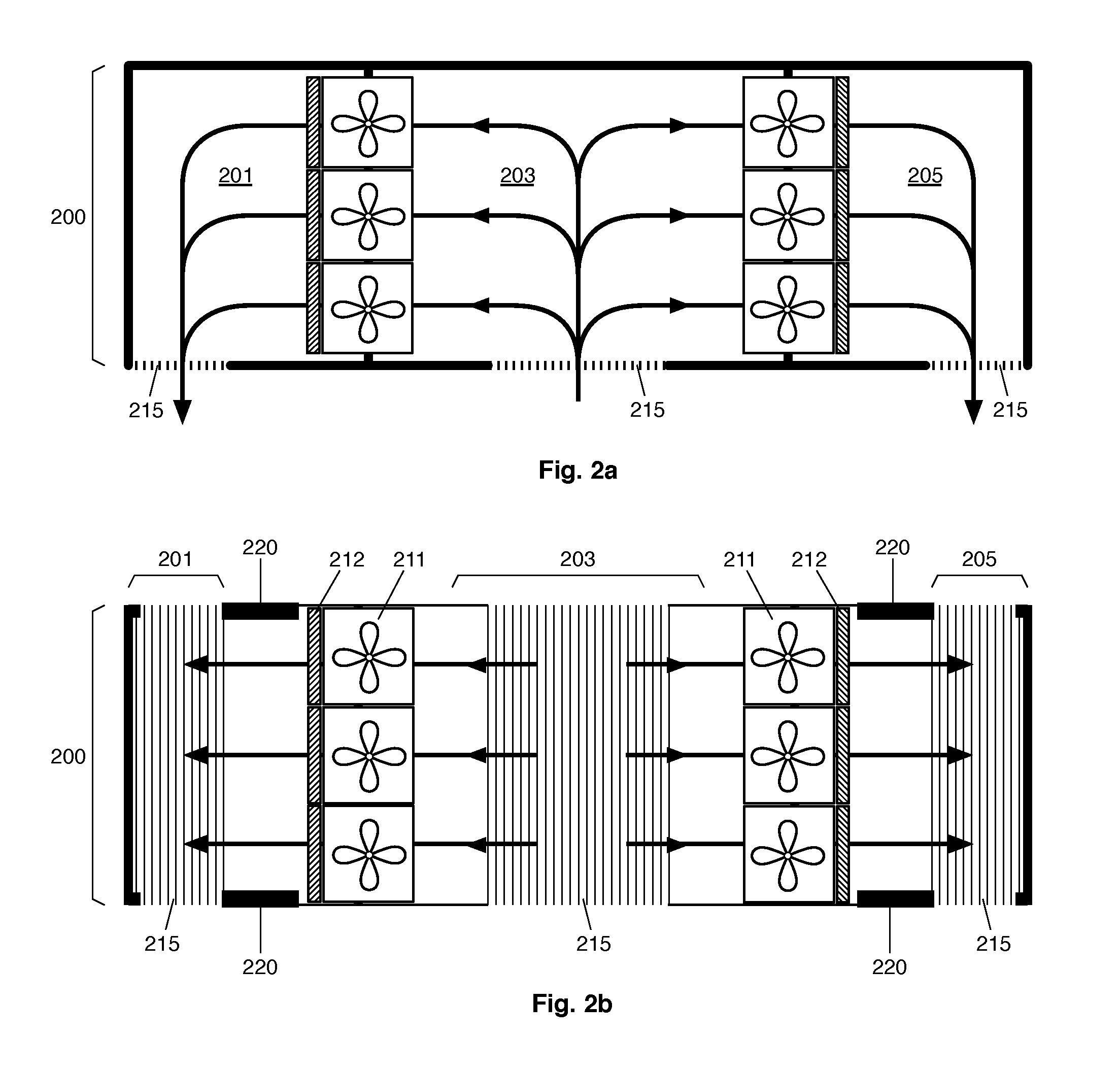
The present invention provides a data center module that solves shortcomings of prior modules by vertically stacking identical modules that exploit two-way vertical airflow and by juxtaposing side-by-side multiple stacks to form spacious, cost-effective, energy efficient, high density, and high resiliency multistory data centers. The data center module is prefabricated and easily transported, similar to a shipping container, and can contain any size of computing cabinets and power distribution and regulation systems. The module is cost-effective as it uses commonly available metal beams and columns, and airflow is managed through large cross-sections and moved using high efficiency and high-capacity variable drive industrial blowers. The data center module also improves resiliency as it allows for the redundant capacity of one module to compensate for the partial failure of a neighbor module.

Problems solved by technology

It's downside, however, is that the dimensions of a standard shipping container can greatly constrain the layout of the computing machinery inside the modules, and can make the access to individual computing cabinets and subsystems more difficult, which in turn impacts the general maintainability of the modular data center.
One way to circumvent this limitation is to place the computing cabinets on sliding rails to move them forward or backward for maintenance, which is hardly practical, albeit possible.
But the next problem is to be able to fit all of the other air handling and air conditioning subsystems within a relatively small space.
And because of this small space, many smaller power and cooling subsystems must be integrated which in turn can make the data center costlier, less efficient, and less reliable.
This approach, however, compounds the accessibility problem, and does nothing to reduce the number of components and reliability issues that can stem from it.
Redundancy is good, but having too many smaller components instead of a smaller number of larger components can be detrimental to efficiency and reliability.
Moreover, making a heap of small data centers does not provide the same flexibility as having one large data center.
Even though it is true that carrying heat in water is much more energy efficient than carrying the same amount of heat into air, using water cooling for high performance computing also has its drawbacks, mostly cost and risk of leaks.

Method used


Image

  • Modular High-Rise Data Centers and Methods Thereof
  • Modular High-Rise Data Centers and Methods Thereof
  • Modular High-Rise Data Centers and Methods Thereof

Examples


Embodiment Construction

[0037]A novel vertical data center modules and a method for their large-scale deployment to allow building of high-rise data centers will be described hereinafter. Although the invention is described in terms of specific illustrative embodiments, it is to be understood that the embodiments described herein are by way of example only and that the scope of the invention is not intended to be limited thereby.

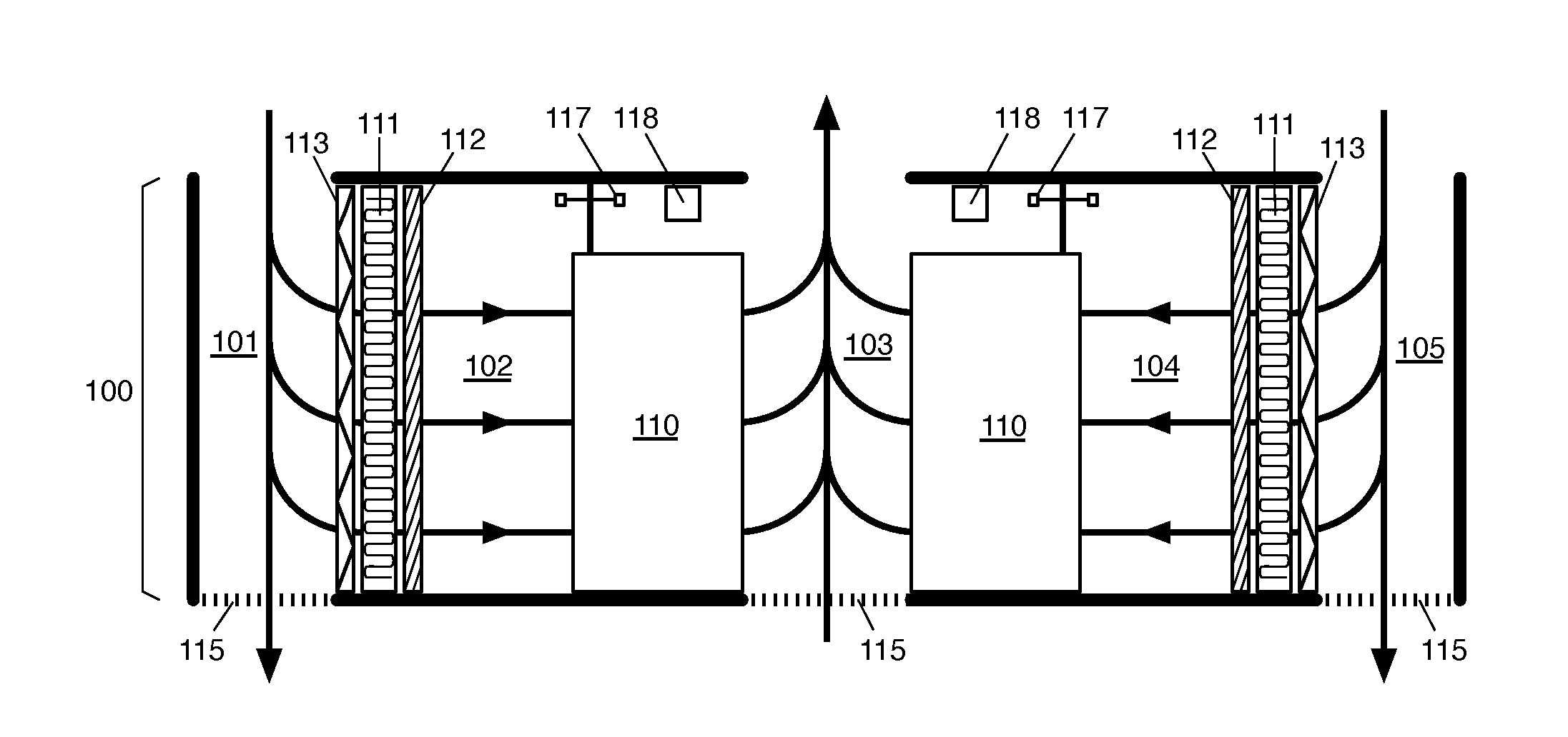
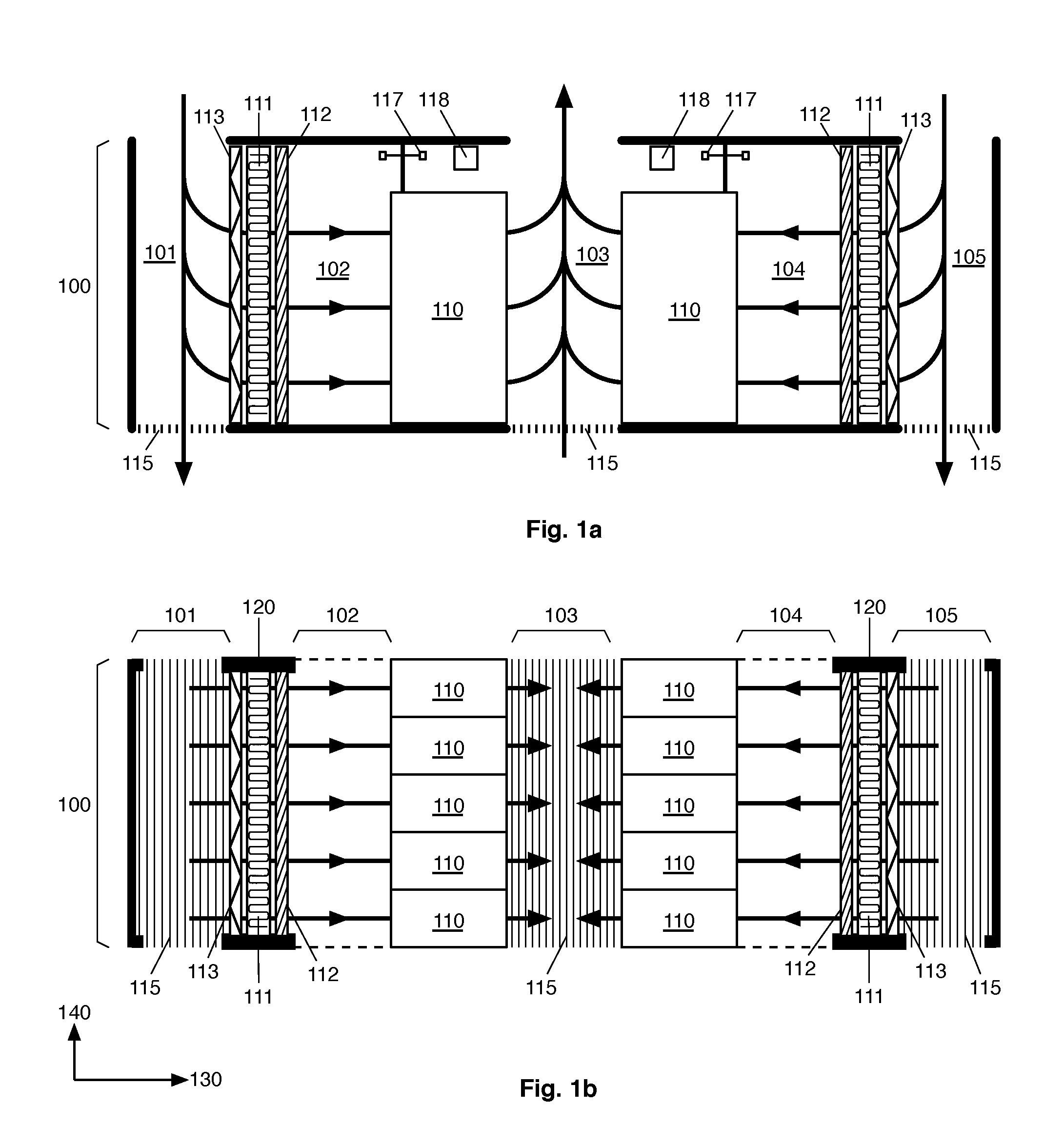
[0038]Now referring to FIGS. 1a and 1b, an embodiment of a data center module 100 large enough to accommodate two rows of computing cabinets 110 is shown. More specifically, FIG. 1a is a side sectional view of the module, while FIG. 1B is a top-sectional view of the same module. The data center module 100 has a long axis 130 and a narrow axis 140. In such an embodiment, a plurality of rows of cabinets 110, typically two, are aligned along the narrow axis of the data center module. In the specific illustrated embodiment, the narrow axis of the data center module is about 10 feet wid...


PUM


Abstract

A system for building multistory data centers using prefabricated modules that can be both juxtaposed side-by-side and stacked vertically, with fluid communication across stories to create two-way vertical airflow for efficient and cost effective high density heat management.

Description

CROSS-REFERENCE TO RELATED APPLICATIONS[0001]The present patent application claims the benefits of priority of U.S. Provisional Patent Application No. 62 / 117,388, entitled “VERTICAL DATA CENTER VENTILATION SYSTEMS AND METHODS FOR MULTI FLOOR BUILDINGS” and filed at the United States Patent and Trademark Office on Feb. 17, 2016.FIELD OF THE INVENTION[0002]The present invention generally relates to data centers and more particularly to data center modules for building high density multistory data centers that incorporate cross-floor vertical airflow for cooling the computing infrastructure.BACKGROUND OF THE INVENTION[0003]In recent years, most of the modular data center market has revolved around the form factor of a shipping container. The main advantage of this form factor is to allow for easy transportation of prefabricated data center modules, complete with their power and cooling subsystems, as well as their computing machinery. This approach allows for rapid and cost effective d...

Claims


Application Information

Patent Timeline
IPC IPC(8): H05K7/20H05K7/14
CPCH05K7/20736H05K7/1488H05K7/1497H05K7/20745H05K7/20136H05K7/2079
Inventor PARIZEAU, MARCMATEU-HUON, ERIC
Owner VERT COM
Learn More