

Robot apparatus
- Summary
- Abstract
- Description
- Claims
- Application Information
AI Technical Summary
Benefits of technology
Problems solved by technology
Method used
Image

Examples
first embodiment
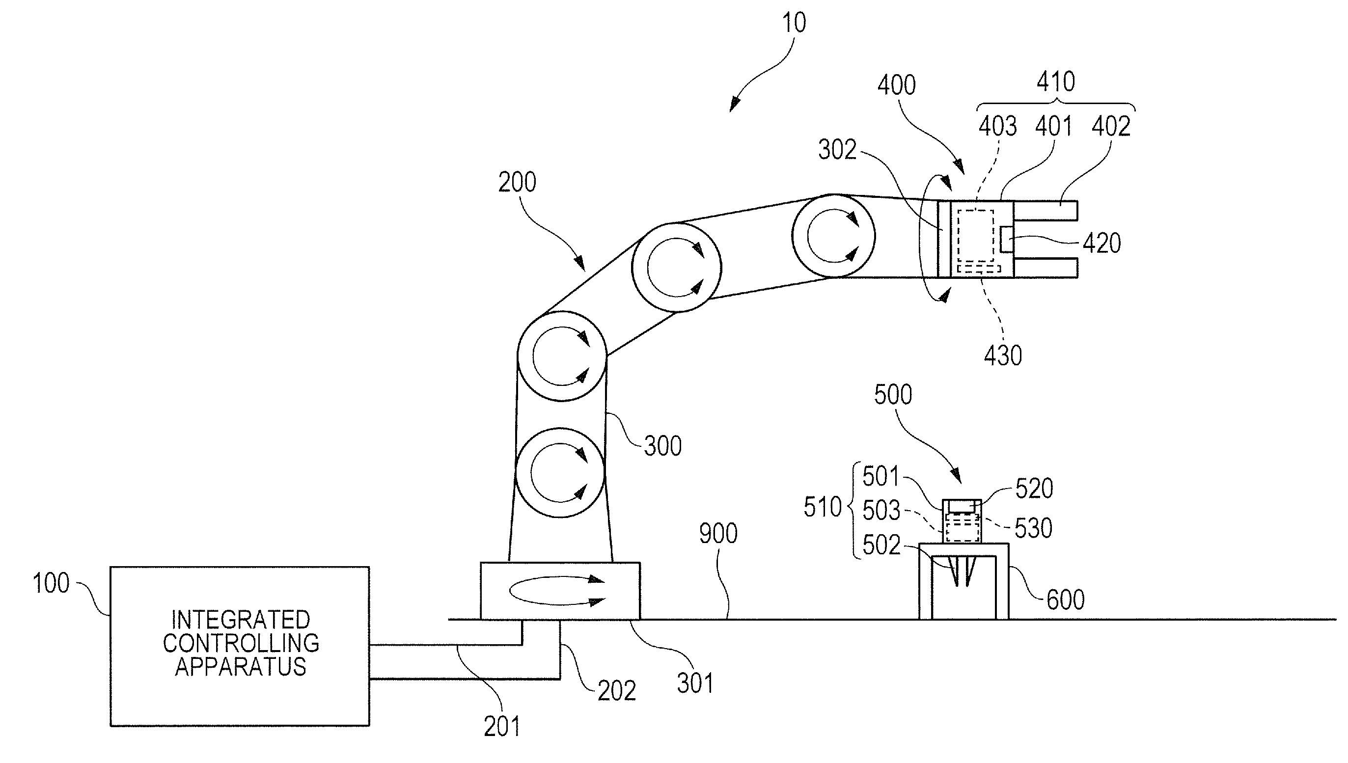
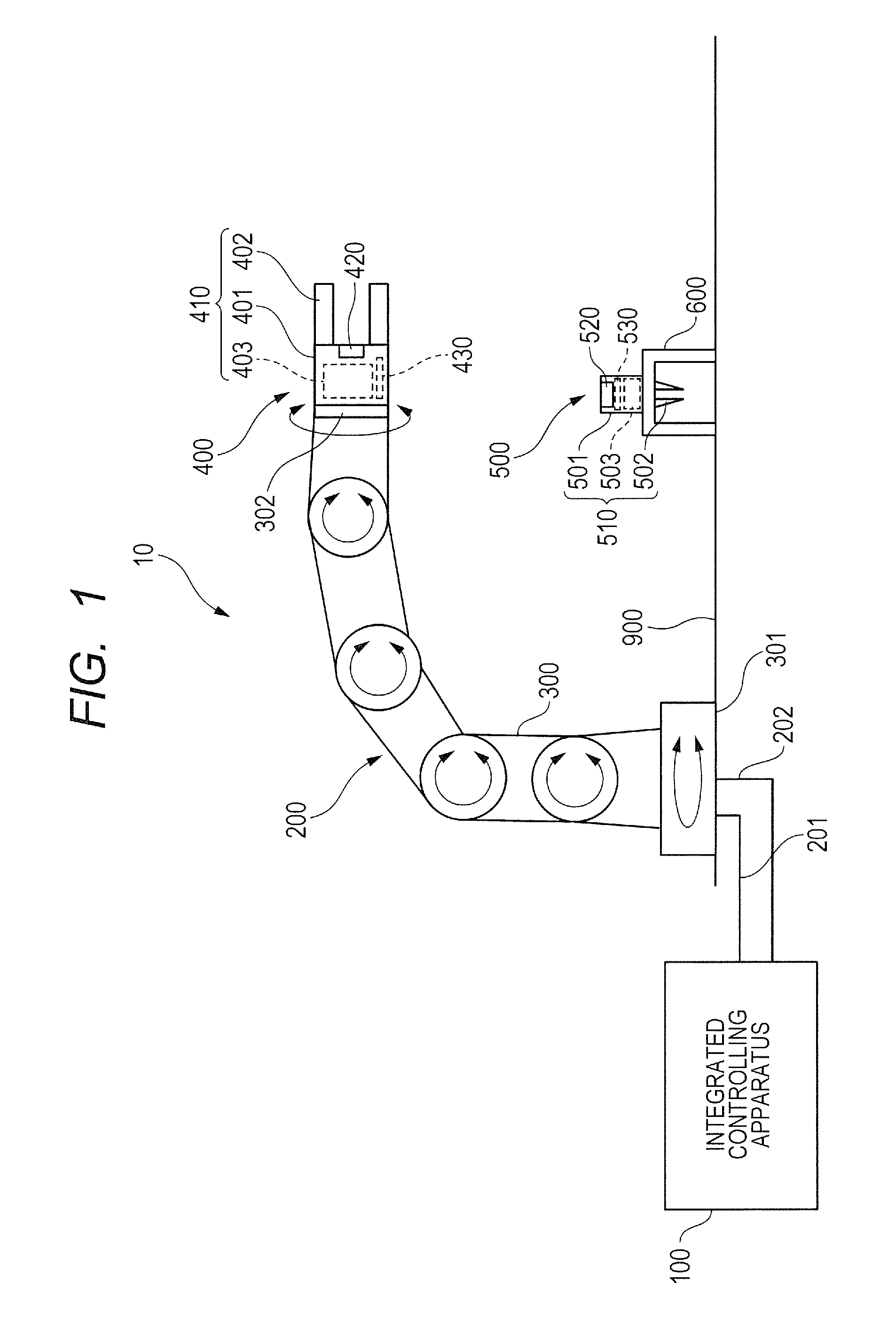
[0028]FIG. 1 is an explanatory view illustrating a robot apparatus according to a first embodiment of the present invention. The robot apparatus 10 includes: a robot 200 having a robot arm (hereafter referred to as “arm”) 300 and a robot hand (hereafter referred to as “hand”) 400; a tool 500 which is attachable to and detachable from the hand 400; and an integrated controlling apparatus 100 which integrally controls these.
[0029]The arm 300 is an electrically-operated robot arm. The arm 300 is a vertical multi-joint robot arm, and is a robot arm which has six joints, specifically, a robot arm which has six axes. A proximal end 301 of the arm 300 is fixed to a trestle 900, and a head 302 of the arm 300 is a free end. The hand 400 is attached to the head 302 of the arm 300. A position and an orientation of the hand 400 can be changed by a rotation or a swing of each joint of the arm 300.
[0030]A tool storage site 600 which supports the tool 500 thereon that has been removed from the han...
second embodiment
[0109]Next, a robot apparatus according to a second embodiment of the present invention will be described. FIG. 6 is a block diagram illustrating an integrated controlling apparatus, a hand and a tool of the robot apparatus according to the second embodiment of the present invention. The configuration of the robot apparatus in the second embodiment is different from that in the first embodiment in the point that the robot apparatus in the second embodiment has a current detecting circuit 450 therein, but except for the point, is similar to the configuration in the first embodiment. Therefore, in the second embodiment, the configurations similar to those in the first embodiment are designated by the same reference numerals, and the description will be omitted.
[0110]The robot apparatus of the second embodiment has further the current detecting circuit 450 which functions as a current detecting unit that detects an electric current which passes through the contact point 423 of the hand...
third embodiment
[0133]Next, a robot apparatus according to a third embodiment of the present invention will be described. Incidentally, the configuration of the robot apparatus is the same as that of the robot apparatus 10 in the first embodiment, and accordingly the detailed description will be omitted.
[0134]In the second embodiment, the case has been described where the robot apparatus 10 has the current detecting circuit 450. However, in the third embodiment, the robot apparatus does not detect the electric current, but stores the value of the electric current in the memory 102 beforehand. Accordingly, in the third embodiment, the current detecting circuit 450 can be omitted which has been described in the second embodiment. The controlling circuit 101 calculates the contact resistance value and determines the contact state similarly to that in the second embodiment.
[0135]The above description will be specifically described below. The memory 102 stores the value of the electric current beforehan...
PUM
 Abstract
Description
Claims
Application Information