Method for bonding components by using energy ray-curable adhesive
- Summary
- Abstract
- Description
- Claims
- Application Information
AI Technical Summary
Benefits of technology
Problems solved by technology
Method used
Image
Examples
Embodiment Construction
[0040]An embodiment of the present invention will be described below with reference to the accompanying drawings. The same reference numerals as in “the Related Art” denote the same components in these drawings. For the sake of a better understanding, these drawings use different scales as appropriate. Although an optical rotary encoder will be taken below as an example of an assembly to which a bonding method according to the present invention is applicable, the present invention is not limited to this.
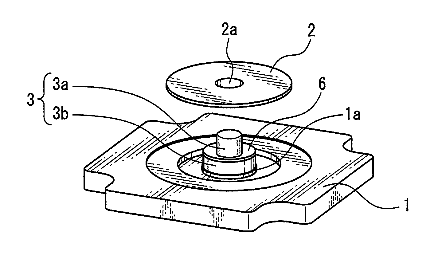
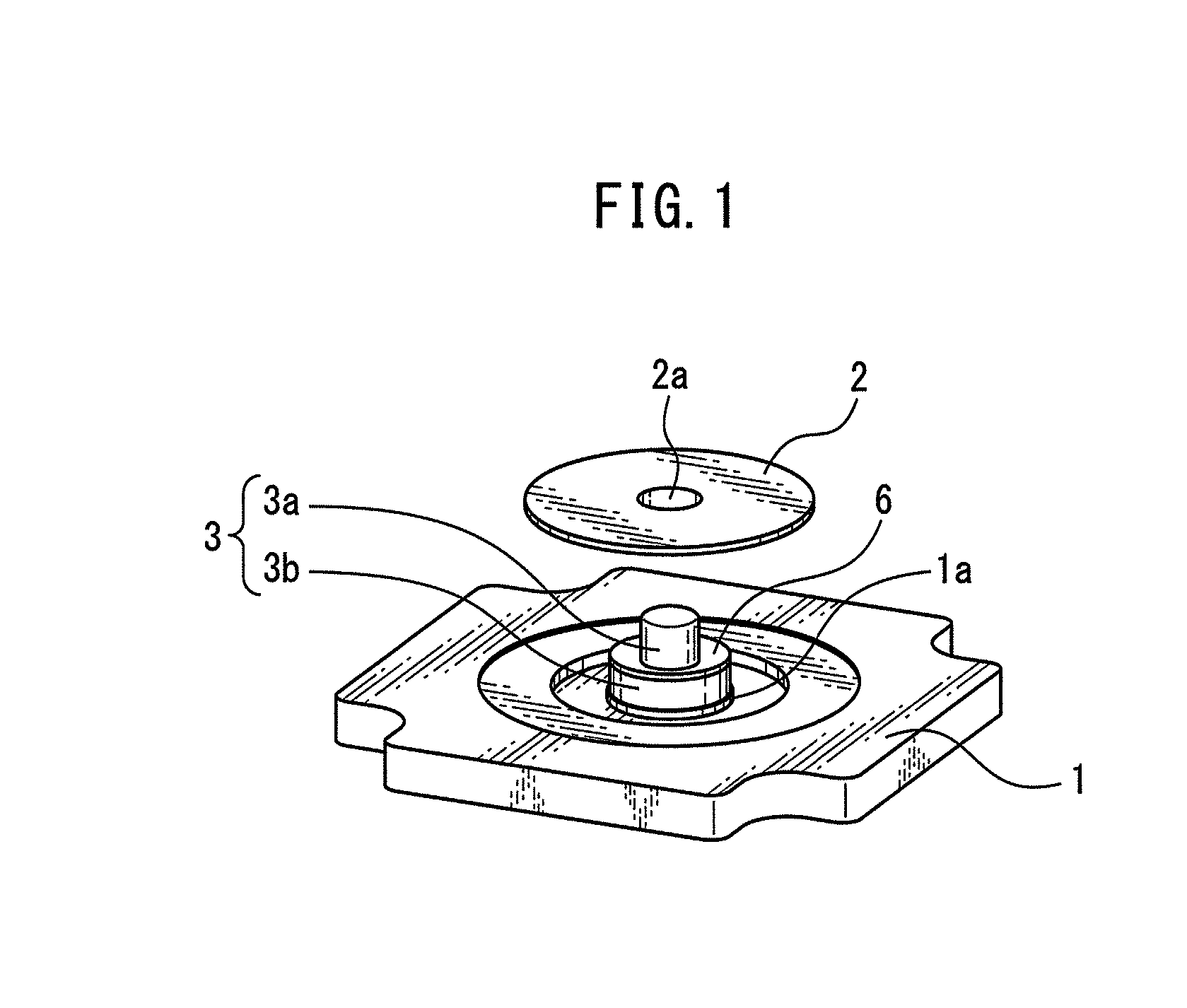
[0041]FIG. 1 is an exploded perspective view illustrating an optical rotary encoder to which a bonding method according to the present invention is applicable.
[0042]In the optical rotary encoder, a first plate-shaped member 1 is opposed to a second plate-shaped member 2, as illustrated in FIG. 1. The second plate-shaped member 2 is implemented in a rotational slit plate. A rotational slit plate for an optical encoder is also called a code plate. A plurality of slits (not illustrated)...
PUM
| Property | Measurement | Unit |
|---|---|---|
| Length | aaaaa | aaaaa |
| Digital information | aaaaa | aaaaa |
| Wavelength | aaaaa | aaaaa |
Abstract
Description
Claims
Application Information
 - R&D
- Intellectual Property
- Life Sciences
- Materials
- Tech Scout
- Unparalleled Data Quality
- Higher Quality Content
- 60% Fewer Hallucinations
Browse by: Latest US Patents, China's latest patents, Technical Efficacy Thesaurus, Application Domain, Technology Topic, Popular Technical Reports.
© 2025 PatSnap. All rights reserved.Legal|Privacy policy|Modern Slavery Act Transparency Statement|Sitemap|About US| Contact US: help@patsnap.com


