Work vehicle

Active Publication Date: 2016-09-01
KOMATSU LTD
View PDF2 Cites 9 Cited by
  • Summary
  • Abstract
  • Description
  • Claims
  • Application Information

AI Technical Summary

Benefits of technology

[0023]As seen from the description above, the work vehicle of the pr

Problems solved by technology

In the work vehicle configured in this manner, earth/sand and/or grit/dust generated during work may be stirred up and enter the cooling core and the like and, while the work vehicle is kept driven for a long time, earth dirt, grease dirt, and/or other foreign matters may be caught on a top sur

Method used


Image

  • Work vehicle
  • Work vehicle
  • Work vehicle

Examples


Embodiment Construction

[0037]In the following, an embodiment of the present invention will be described based on the drawings. The present embodiment will be described mainly with reference to a bulldozer as an example of the work vehicle.

[0038]

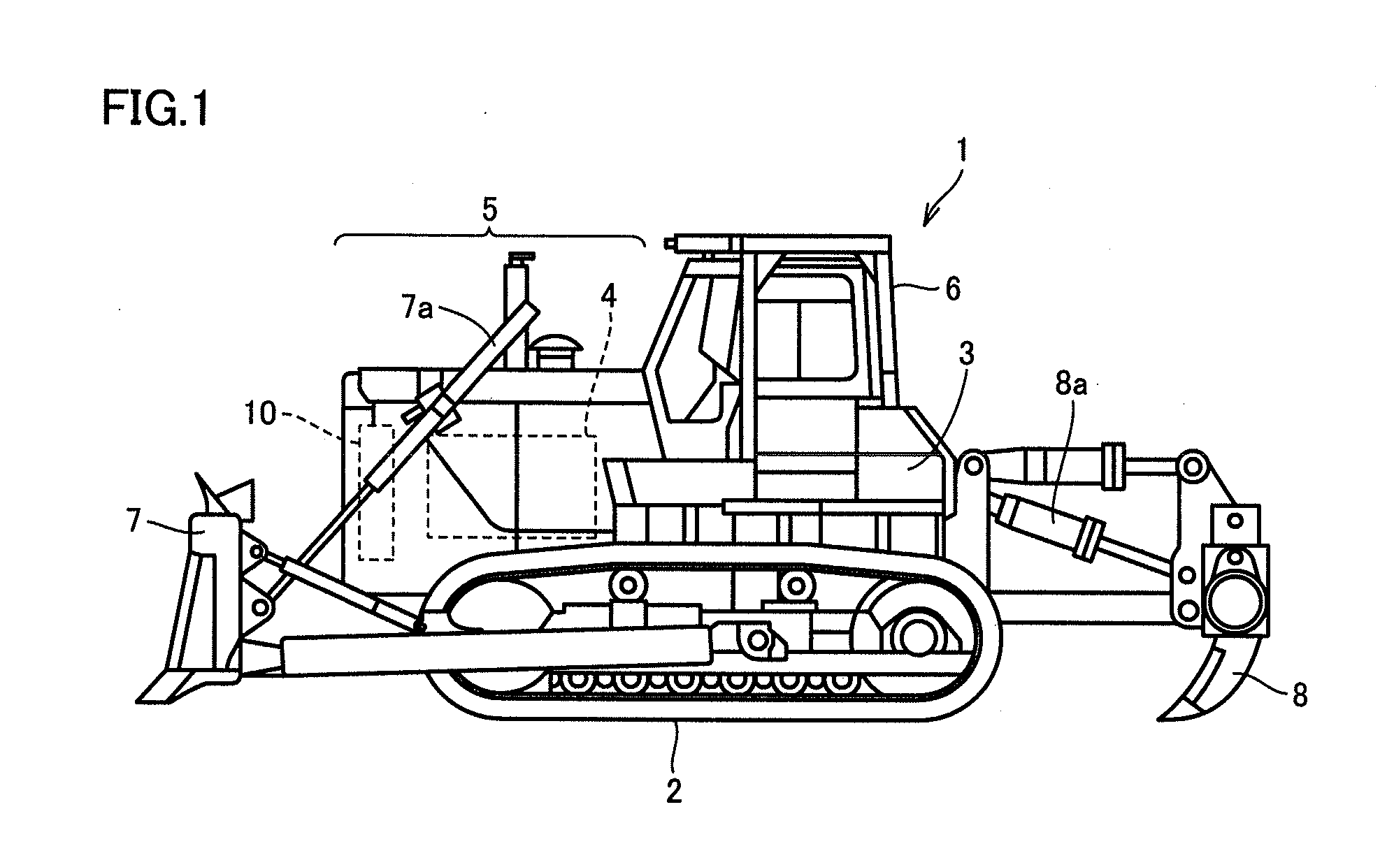
[0039]FIG. 1 is a side view of a bulldozer 1.

[0040]As shown in FIG. 1, bulldozer 1 includes a traveling unit 2, a body 3, a blade 7, a ripper 8, and a cab 6.

[0041]Body 3 is provided on traveling unit 2.

[0042]Traveling unit 2 is provided under body 3 in such a manner that enables traveling unit 2 to travel, and has a pair of endless belts rotated to enable the traveling unit to travel on an irregular ground.

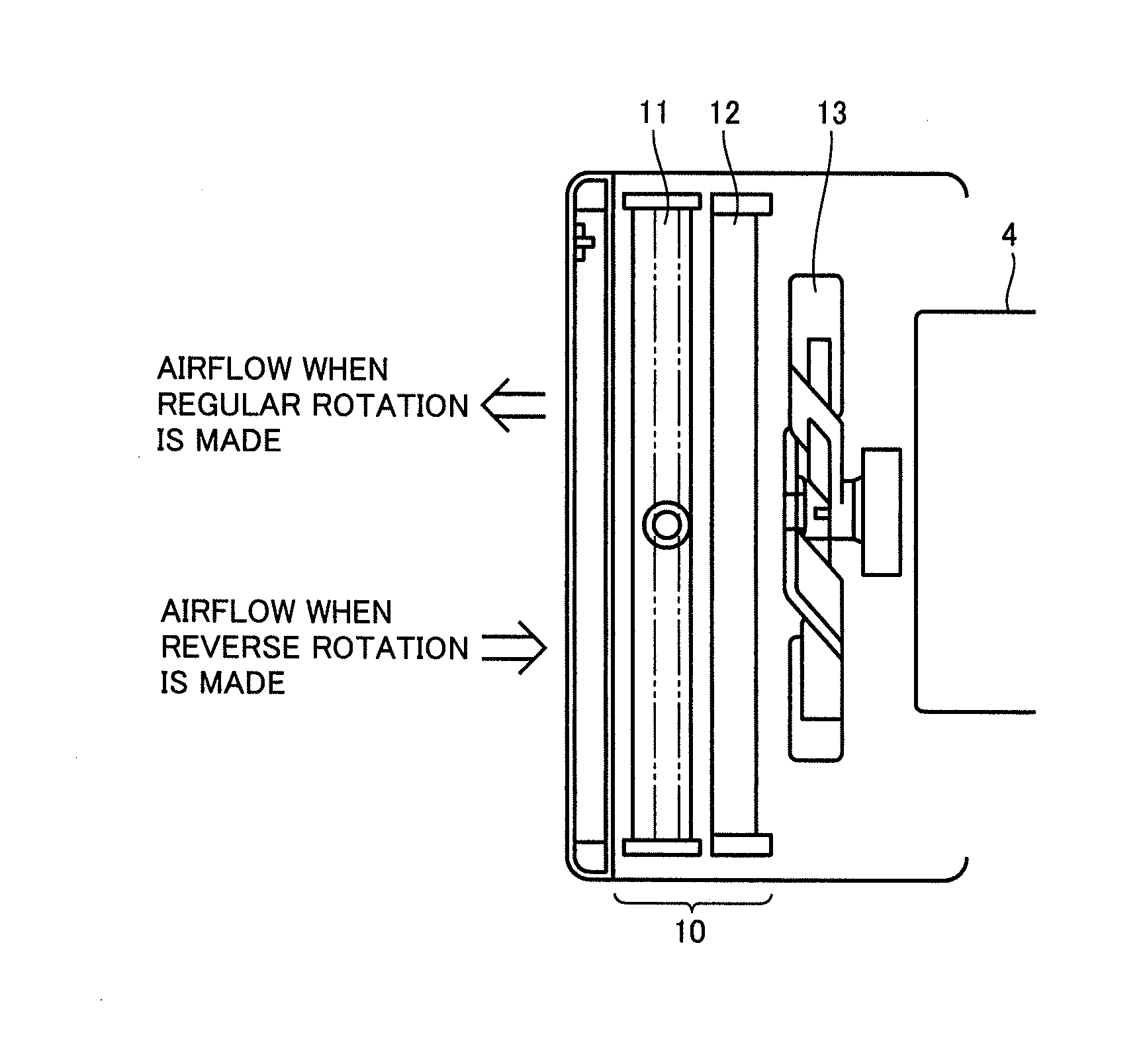
[0043]Body 3 is mounted with an engine 4 and a cooling core 10.

[0044]Engine 4 is provided in an engine compartment located in a front portion of body 3. By way of example, engine 4 is a diesel engine.

[0045]Cooling core 10 includes at least one of a radiator which is used for cooling a coolant of engine 4, an oil cooler which cools a hydraulic oil, and the like.

[0...


PUM


Abstract

A work vehicle of the present invention includes an engine, a cooling core, a fan, a hydraulic drive unit, and an idle reduction execution unit. The cooling core is mounted in the work vehicle. The fan is configured to blow air to the cooling core and to be capable of making regular and reverse rotations. The hydraulic drive unit is configured to drive the fan by driving the engine. The idle reduction execution unit is configured to stop the engine based on a state of rotation of the fan caused by the hydraulic drive unit and based on an idle state. The idle reduction execution unit stops the engine on a condition that the fan makes regular rotation and the idle state has continued for a predetermined time, and does not stop the engine on a condition that the fan makes reverse rotation.

Description

TECHNICAL FIELD[0001]The present invention relates to a work vehicle, and particularly relates to a work vehicle having a cooling core.BACKGROUND ART[0002]A work vehicle such as bulldozer is mounted with a work implement such as blade, a hydraulic pump driven by an engine, a fan driven by a hydraulic oil emitted from the hydraulic pump, and a cooling core for cooling a coolant or the like flowing to the engine, by means of an airflow generated by the fan. By way of example, the cooling core includes a radiator, an oil cooler, or the like.[0003]In the work vehicle configured in this manner, earth / sand and / or grit / dust generated during work may be stirred up and enter the cooling core and the like and, while the work vehicle is kept driven for a long time, earth dirt, grease dirt, and / or other foreign matters may be caught on a top surface of cooling fin serving as a component of the cooling core, which may possibly result in clogging with the dirt sticking to and deposited on the sur...

Claims


Application Information

Patent Timeline
IPC IPC(8): E02F9/22F15B11/08F01P1/06F01P5/04E02F9/08E02F9/20
CPCE02F9/226E02F9/0866E02F9/2066F15B2211/66F01P5/04F15B11/08E02F3/7609F01P1/06E02F3/7604E02F9/0891E02F9/2246E02F9/2292E02F9/2296F01P5/043F01P2011/063F02D29/02F02D29/04F02N11/0818
Inventor KURE, KAZUKI
Owner KOMATSU LTD
Why Eureka
Try Eureka