Blade for a rotor of a wind turbine provided with barrier generating means

a technology of wind turbine and generating means, which is applied in the direction of wind energy generation, mechanical equipment, machines/engines, etc., can solve the problems of increasing the drag (and in some cases even the lift-to-drag ratio) of the blade, and achieves the effect of effectively preventing cross-flow and not impairing the functionality of the airfoil region

Inactive Publication Date: 2016-09-01
LM GLASSFIBER
View PDF8 Cites 6 Cited by
  • Summary
  • Abstract
  • Description
  • Claims
  • Application Information

AI Technical Summary

Benefits of technology

[0013]According to a first aspect of the invention, the object is obtained by a first barrier generating means being arranged on the suction side of the blade in the transition region or in the airfoil region in a part nearest the transition region, the first barrier generating means being adapted to generating a barrier of airflow along a first strip, which extends essentially in a transverse direction of the blade on the suction side of the blade. Thus, the first barrier generating means are arranged in a zone comprising the transition region and a part of the airfoil region nearest the transition region. Preferably, the first barrier means are arranged in a first zone positioned in a zone of a cross-flow. This cross-flow may be inherent to the design of the blade during use of the blade in a wind turbine rotor. The barrier of airflow must be of sufficient strength and length so as to effectively reduce the cross-flow. Cross-flows arising in a region of detached airflow, for instance due to pressure differentials caused by different incident airflow speeds at different blade radii, and which especially arise in the area of the blade root, can thereby be reduced or prevented by the barrier of airflow preventing the cross-flows from passing the first zone. Thereby, it is possible to prevent a detached flow from propagating in the longitudinal or radial direction of the blade towards the blade tip and especially preventing the detached flow from propagating along the profiled region of the blade.
[0014]According to a first advantageous embodiment, the first strip has a width, which lies in an interval between 20 cm and 2 m, or between 25 cm and 1.5 m, or between 30 cm and 1 m. Typically, the longitudinal extent of the strip is about 50 cm. According to a second advantageous embodiment, the first barrier generating means are with no barrier generating means on radial sides of the first barrier generating means, i.e. no barrier generating means abut the first strip or the first barrier generating means. The use of barrier generating means may increase the drag (and in some cases even the lift to drag ratio) of the blade in the zone, in which the barrier generating means is arranged. By arranging the barrier generating means in strips only, it is ensured that the barrier generating means only increases the drag in a small region of the blade.
[0016]According to an advantageous embodiment, the first barrier generating means is arranged in the transition region only. Thereby, the barrier generating means does not impair the functionality of the airfoil region of the blade. Preferably, the barrier generating means is arranged so that a cross-flow of detached flow does not propagate into the airfoil region.
[0017]According to a preferred embodiment, the barrier generating means is adapted to generate a barrier of airflow extending at least from an area of maximum relative profile thickness and the trailing edge of the blade. I.e. the barrier extends at least from an area corresponding to the position of maximum thickness (or equivalently the position of the maximum thickness-to-chord ratio) of an airfoil profile to the trailing edge. Thereby, the barrier generating means effectively prevents cross-flows running on the suction side of the blade through this region of the profile, where separation usually occurs and which—partly due to the centrifugal force—can propagate toward the blade tip.
[0027]According to a preferred embodiment, the first zone and / or the additional zone are arranged in the airfoil region in a part nearest the hub. That is, the zone is located just beyond the transition zone. This is efficient for interrupting an already extant cross-flow coming from the root area.
[0029]In another embodiment according to the invention, the first zone and / or the second zone comprise a Gurney flap arranged at the trailing edge and on the pressure side of the blade. This may further improve the performance of the blade. Usually the Gurney flap is used in addition to the barrier generating means. However, in situations where the separation occurs near the trailing edge, the Gurney flap may be sufficient in itself.

Problems solved by technology

The use of barrier generating means may increase the drag (and in some cases even the lift to drag ratio) of the blade in the zone, in which the barrier generating means is arranged.

Method used


Image

  • Blade for a rotor of a wind turbine provided with barrier generating means
  • Blade for a rotor of a wind turbine provided with barrier generating means
  • Blade for a rotor of a wind turbine provided with barrier generating means

Examples


first embodiment

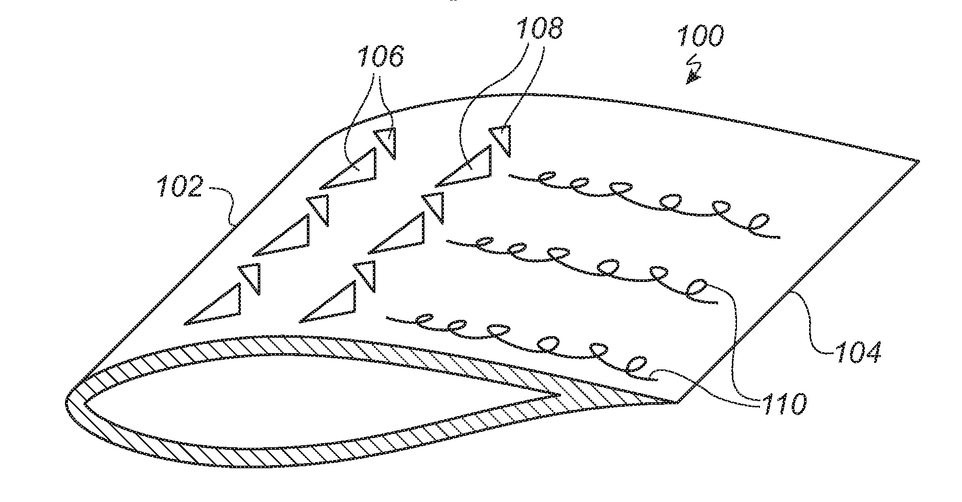
[0052]FIG. 4 shows a blade section 100 (i.e. of the first zone or the second zone) of a first embodiment with barrier generating means according to the invention. The profile has a leading edge 102 and a trailing edge 104, and a first set of vortex generators 106 and a second set of vortex generators 108 are arranged on the suction side of the blade section 100. The vortex generators 106, 108 are here depicted as being of the vane type, but may be any other type of vortex generator. The vortex generators 106, 108 generate a barrier of airflow consisting of coherent turbulent structures, i.e. vortices propagating at the surface of the blade towards the trailing edge 104, which prevent cross-flows of detached airflow to propagate beyond the zone in which the vortex generators 106, 108 are arranged.

second embodiment

[0053]FIG. 5 shows a profile 200 of a second embodiment with barrier generating means according to the invention. In this embodiment, the barrier generating means consists of a number of ventilation holes 206 for blowing or suction between an interior of the blade and an exterior of the blade. The ventilation holes 206 can be utilised to create a belt of attached flow. The air vented from the ventilation holes 206 are used to energise and re-energise the boundary layer in order to maintain the flow attached to the exterior surface of the blade. The belt of attached flow acts as a barrier to a separated cross-flow by “catching” the cross-flow, which is thus forced to join the attached flow towards the trailing edge 204 instead of flowing outwards towards the tip end. The ventilation holes 206 are in this embodiment arranged substantially tangentially to the surface of the profile 200. The ventilation holes 206 may be provided as a series of holes in the longitudinal direct ion of the...

fourth embodiment

[0055]FIG. 7 shows a profile 400 of a fourth embodiment with barrier generating means according to the invention. In this embodiment, the barrier generating means consists of a slat 406 arranged at the leading edge 402 of the profile 400. The slat points downwards towards the pressure side of the profile 402 and is utilised to create a local change in the inflow angle and airfoil lift, thereby causing the flow to remain attached to the surface of the blade. This attached “tunnel” for the flow creates a barrier, where the cross-flow is caught and thus forced to join the attached flow towards the trailing edge 404 instead of flowing outwards towards the tip end.


PUM


Abstract

A blade for a rotor of a wind turbine has a profiled contour including a leading edge and a trailing edge as well as a pressure side and a suction side, the profiled contour generating lift when impacted by an incident airflow. The profiled contour is divided into a root region with a substantially circular profile closest to the hub, an airfoil region with a lift generating profile furthest away from the hub, and a transition region between the root and airfoil regions. The suction side has a first zone which extends substantially in the direction of the incident airflow, and which is positioned in a zone of a cross-flow. The first zone includes a first barrier generating means adapted to generating a barrier of airflow, which extends essentially in the direction of the incident airflow and is of sufficient strength and length so as to effectively reduce the cross-flow.

Description

TECHNICAL FIELD[0001]The present invention relates to a blade for a rotor of a wind turbine having a substantially horizontal rotor shaft, said rotor comprising a hub, from which the blade extends substantially in a radial direction when mounted to the hub, the blade comprising: a profiled contour including a leading edge and a trailing edge as well as a pressure side and a suction side, the profiled contour when being impacted by an incident airflow generating a lift, wherein the profiled contour is divided into: a root region with a substantially circular profile closest to the hub, an airfoil region with a lift generating profile furthest away from the hub, and a transition region between the root region and the airfoil region, the profile of the transition region gradually changing in the radial direction from the circular profile of the root region to the lift generating profile of the airfoil region.BACKGROUND[0002]Horizontal axis wind turbines comprise a rotor provided with a...

Claims


Application Information

Patent Timeline
Patent Type & Authority Applications(United States)
IPC IPC(8): F03D1/06F03D7/02
CPCF03D7/0232F03D1/0633F03D1/0641F03D7/0228F03D7/0252F03D7/0256F05B2240/32F05B2260/90F05B2270/20Y02E10/72F05B2240/3062
Inventor FUGLSANG, PETERBOVE, STEFANO
Owner LM GLASSFIBER
Why Eureka
Try Eureka