Display panel with touch detection function
- Summary
- Abstract
- Description
- Claims
- Application Information
AI Technical Summary
Benefits of technology
Problems solved by technology
Method used
Image
Examples
first embodiment
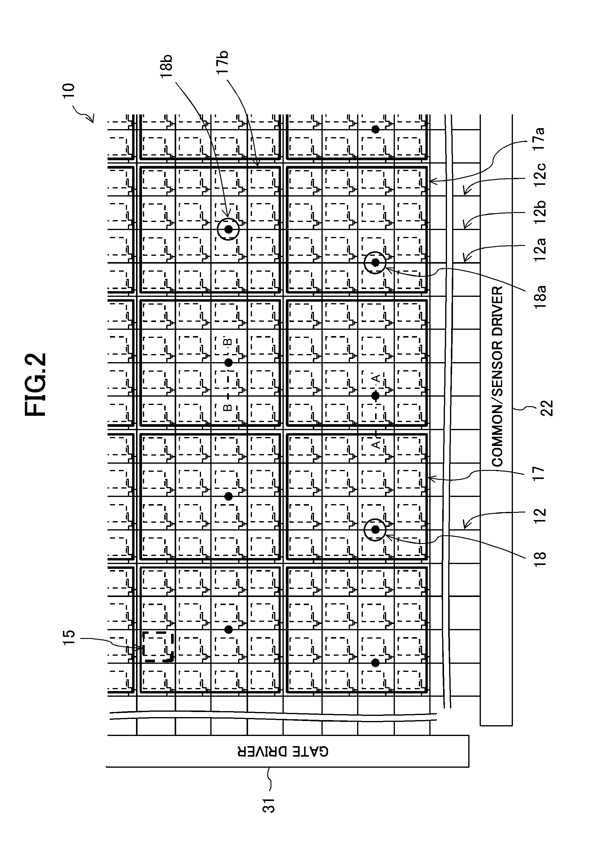
[0059]FIG. 4 is a sectional view taken along the line A-A′ of FIG. 2 in the display panel 10 of the first embodiment. The display panel 10 includes a TFT substrate 200, a color filter (CF) substrate 300, and a liquid crystal layer 400 sandwiched between both the substrates.
[0060]In the TFT substrate 200, the plurality of gate signal lines 13 (not shown) are formed on a glass substrate 201, a first insulating film 202 is formed so as to cover the plurality of gate signal lines 13, the plurality of data signal lines 11 are formed on the first insulating film 202, a second insulating film 203 is formed so as to cover the plurality of data signal lines 11, and a third insulating film 204 is formed on the second insulating film 203. The third insulating film 204 is made of, for example, a photosensitive organic material containing acrylic as a main component. The plurality of common electrodes 17 (sensor electrodes) are formed on the third insulating film 204, a fourth insulating film 20...
second embodiment
[0063]FIG. 5 is a sectional view taken along the line A-A′ of FIG. 2 in a display panel 10 of the second embodiment.
[0064]In the TFT substrate 200, the plurality of gate signal lines 13 (not shown) are formed on the glass substrate 201, the first insulating film 202 is formed so as to cover the plurality of gate signal lines 13, the plurality of data signal lines 11 are formed on the first insulating film 202, the second insulating film 203 is formed so as to cover the plurality of data signal lines 11, and the third insulating film 204 (organic insulating film) is formed on the second insulating film 203. The plurality of sensor electrode lines 12 are formed on the third insulating film 204, the fourth insulating film 205 is formed so as to cover the plurality of sensor electrode lines 12, and the through hole 18 is formed through a part of the fourth insulating film 205. The sensor electrode line 12 is formed at a position at which the sensor electrode line 12 overlaps with the da...
third embodiment
[0067]FIG. 6 is a sectional view taken along the line A-A′ of FIG. 2 in a display panel 10 of the third embodiment. The display panel 10 of the third embodiment is formed as follows. In the display panel 10 of the second embodiment, a plurality of adhesion layers 207a are formed on the third insulating film 204, and the sensor electrode lines 12 are formed on the respective adhesion layers 207a. The adhesion layer 207a and the sensor electrode line 12 are formed at a position at which the adhesion layer 207a and the sensor electrode line 12 overlap with the data signal line 11 in plan view. The adhesion layer 207a is made of, for example, indium tin oxide (ITO), which is a transparent conductive material.
[0068]With the above-mentioned configuration, the above-mentioned effects in the display panel 10 of the second embodiment can be obtained, and it is possible to prevent film removal of the sensor electrode line 12 from the third insulating film 204.
PUM
 Abstract
Description
Claims
Application Information
 - R&D
- Intellectual Property
- Life Sciences
- Materials
- Tech Scout
- Unparalleled Data Quality
- Higher Quality Content
- 60% Fewer Hallucinations
Browse by: Latest US Patents, China's latest patents, Technical Efficacy Thesaurus, Application Domain, Technology Topic, Popular Technical Reports.
© 2025 PatSnap. All rights reserved.Legal|Privacy policy|Modern Slavery Act Transparency Statement|Sitemap|About US| Contact US: help@patsnap.com


