Display device including antenna and method of fabricating the same

Active Publication Date: 2021-01-14
LG DISPLAY CO LTD
View PDF0 Cites 3 Cited by
  • Summary
  • Abstract
  • Description
  • Claims
  • Application Information

AI Technical Summary

Benefits of technology

The present disclosure provides a display device with an antenna and a method of fabricating the device that reduces the thickness of the display panel and mobile terminal. It also reduces the deterioration of touch performance, display quality, and stabilizes the antenna's performance by connecting it directly to a communication circuit. Overall, this technology improves the efficiency and reliability of display devices with antennas.

Problems solved by technology

In addition, since the antenna pattern of the transparent film as the antenna is disposed to overlap a display area of the display panel and a touch area of the touch panel, a touch performance and a display quality are deteriorated.
Moreover, since an electrode (a cathode) of the display panel is used as a ground layer, a ground voltage of the antenna becomes unstable.

Method used


Image

  • Display device including antenna and method of fabricating the same
  • Display device including antenna and method of fabricating the same
  • Display device including antenna and method of fabricating the same

Examples


first embodiment

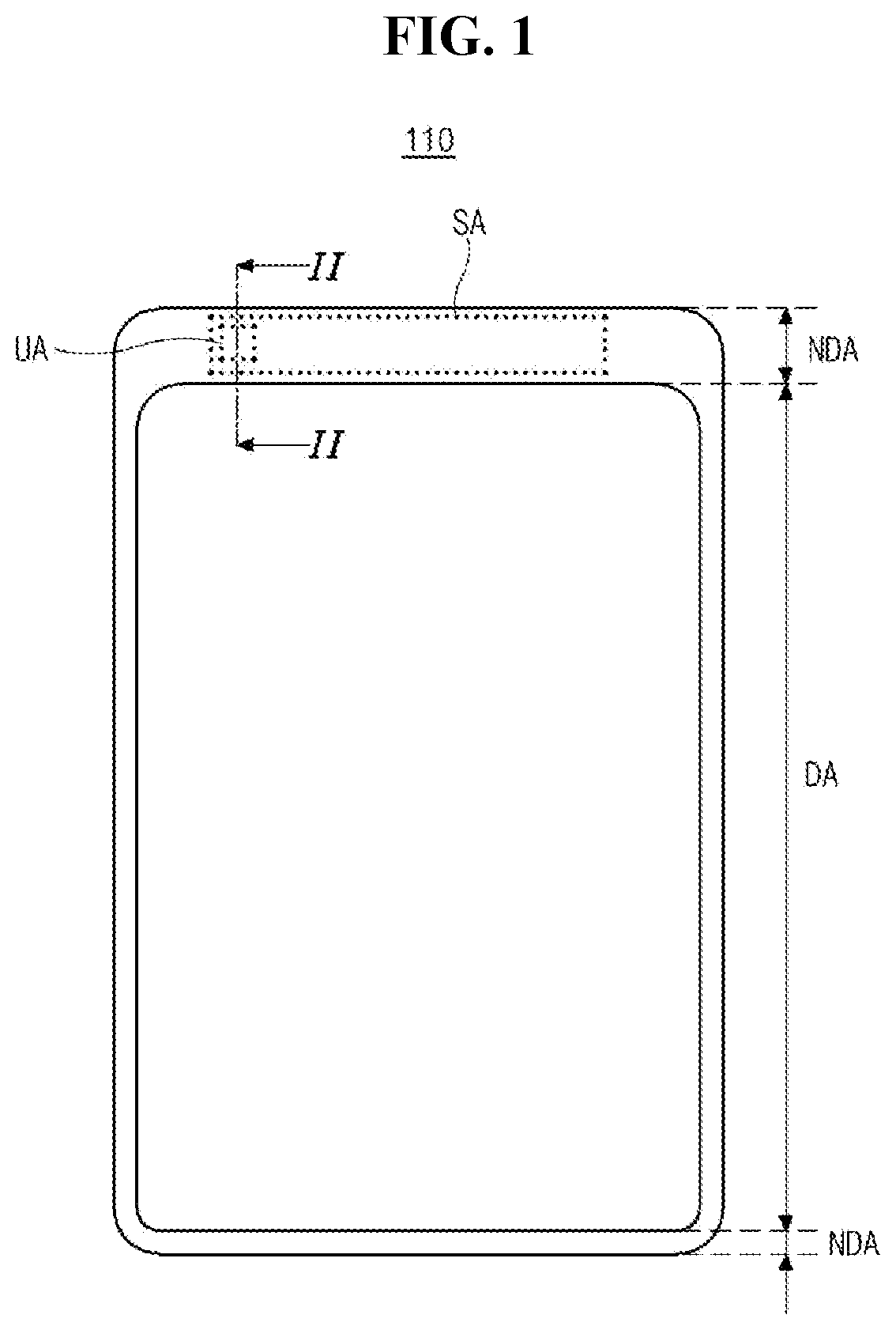
[0033]FIG. 1 is a plan view showing a display device including an antenna according to the present disclosure.

[0034]In FIG. 1, a display device 110 according to a first embodiment of the present disclosure includes a display panel DP (of FIG. 2) displaying an image, a circuit unit supplying a source voltage and a signal to the display panel DP and a frame 386 (of FIG. 7) surrounding and supporting the display panel DP and the circuit unit.

[0035]The display panel DP includes a display area DA including a plurality of pixels P and substantially displaying an image and a non-display area NDA having a plurality of pads and surrounding the display area DA.

[0036]Here, a slot antenna SA is disposed in the non-display area NDA of the display panel DP and includes at least one unit antenna UA of a coplanar waveguide (CPW) structure and a reflector RF (of FIG. 5).

[0037]For example, the slot antenna SA may include three or more unit antennas UA for a five-generation (5G) service of a millimete...

second embodiment

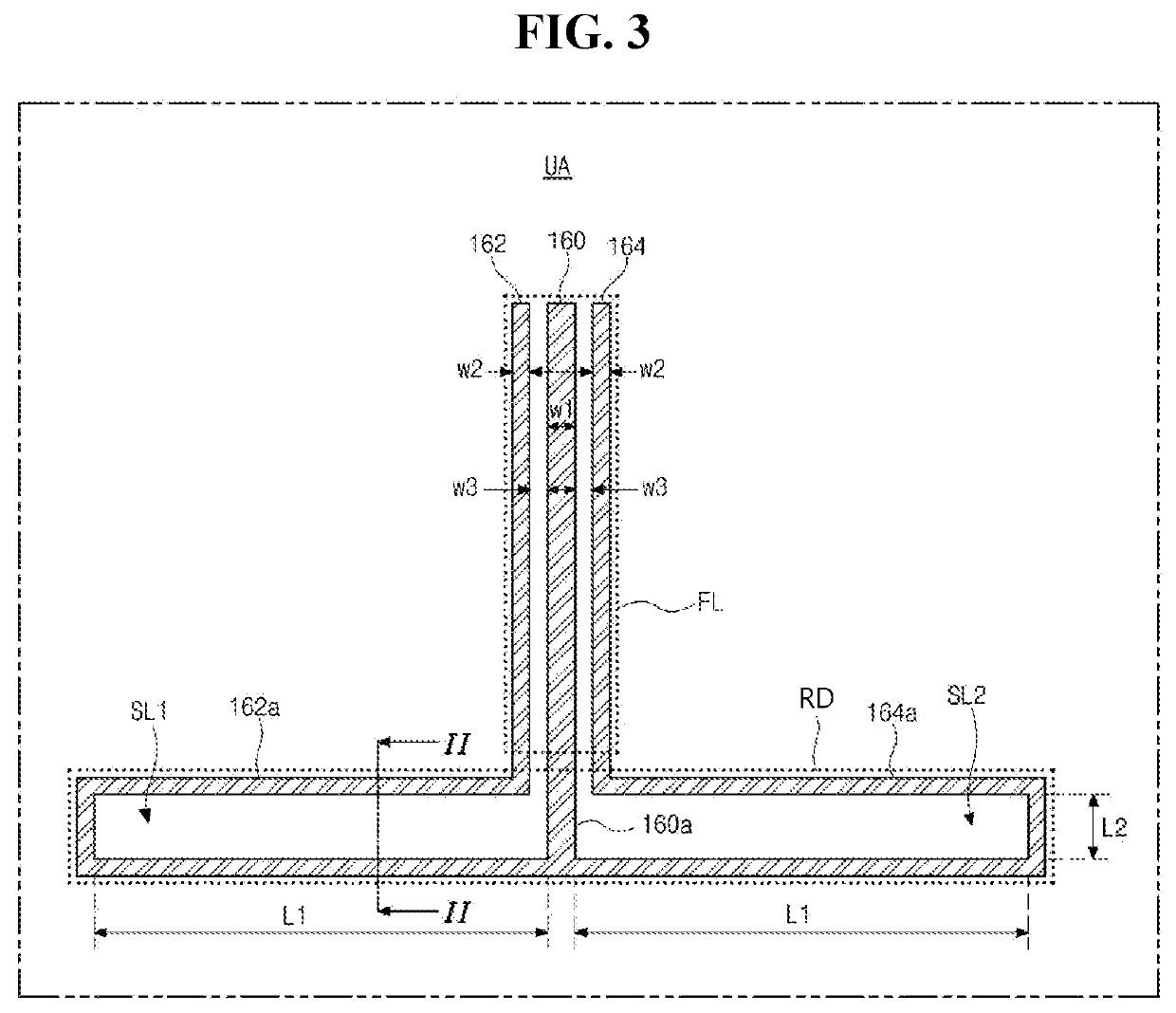
[0076]FIG. 4 is a plan view showing a unit antenna of a display device including an antenna according to the present disclosure.

[0077]In FIG. 4, at least one unit antenna UA of a slot antenna SA disposed on a display panel DP of a display device according to a second embodiment of the present disclosure includes a feed line FL and a radiator RD.

[0078]The feed line FL includes a transmission line 260 transmitting a communication signal and first and second ground lines 262 and 264 having a ground voltage and disposed at left and right sides, respectively, of the transmission line 260.

[0079]First end portions of the transmission line 260 and the first and second ground lines 262 and 264 may be connected to pads in a non-display area NDA of the display panel DP to receive the communication signal and the ground voltage, respectively, from a communication circuit unit 180 (of FIG. 5).

[0080]The transmission line 260 is disposed at a biased portion from a central portion of the unit anten...

third embodiment

[0122]FIG. 7 is a cross-sectional view showing a display device including an antenna according to the present disclosure. For illustration's convenience, a substrate 320, a passivation layer 332 and a unit antenna UA of a display panel DP of a display device 310 are shown and other elements of the display panel DP are not shown in FIG. 7.

[0123]In FIG. 7, a display device 310 according to the third embodiment of the present disclosure includes a display panel DP displaying an image, a circuit unit supplying a source voltage and a signal to the display panel DP and a frame 386 surrounding and supporting the display panel DP and the circuit unit.

[0124]The display panel DP includes a substrate 320, a driving thin film transistor DT, an emitting diode ED and at least one unit antenna UA. The display panel DP may further include other elements in another embodiment.

[0125]A reflection preventing layer 370 is disposed in a display area DA on a top surface of the display panel DP. A reflecti...


PUM


Abstract

A display device includes: a substrate having a display area and a non-display area at a periphery of the display area; at least one unit antenna disposed in the non-display area on the substrate and having a coplanar wave guide structure; and a communication circuit unit transmitting and receiving a communication signal with the at least one unit antenna.

Description

CROSS REFERENCE TO RELATED APPLICATIONS[0001]The present application claims the priority benefit of Republic of Korea Patent Application No. 10-2019-0084160 filed in Republic of Korea on Jul. 12, 2019, which is hereby incorporated by reference in its entirety.BACKGROUNDTechnical Field[0002]The present disclosure relates to a display device including an antenna, and more particularly, to a display device including a slot antenna of a coplanar waveguide structure and a method of fabricating the display device.Discussion of the Related Art[0003]A mobile terminal is a portable terminal capable of transmitting and receiving a voice, a character and an image data through a wireless communication.[0004]The mobile terminal includes a touch panel, a display panel and an antenna. The touch panel receives an information from a user, the display panel transmits an information to a user, and an antenna transmits and receives a wireless signal with a free space.[0005]Although the antenna has been...

Claims


Application Information

Patent Timeline
IPC IPC(8): H01Q21/06H01Q1/38H01Q1/22H01Q13/22H01Q15/14H01Q19/10
CPCH01Q21/068H01Q1/38H01Q19/10H01Q13/22H01Q15/14H01Q1/2258H01Q1/22H01Q1/50H01Q1/36H01Q1/48H10K59/00H10K59/12H10K59/1201H01Q13/16H01Q1/243H04M1/0249H04M1/026H01Q1/46
Inventor JANG, LAE-BONGJO, SOO-IN
Owner LG DISPLAY CO LTD
Why Eureka
Try Eureka