Applications of electro-optic displays

a technology of electro-optic displays and displays, applied in the field of applications of electro-optic displays, can solve the problems of inadequate service life of these displays, preventing their widespread use, and gas-based electrophoretic media being susceptible to the same types of problems

Active Publication Date: 2016-09-08
E INK CORPORATION
View PDF8 Cites 20 Cited by
  • Summary
  • Abstract
  • Description
  • Claims
  • Application Information

AI Technical Summary

Benefits of technology

[0055]bringing the portable token adjacent one of the variable direction signs so that the one variable direction sign receives at least part of the information id

Problems solved by technology

Nevertheless, problems with the long-term image quality of these displays have prevented their widespread usage.
For example, particles that make up electrophoretic displays tend to settle, resulting in inadequate service-life for these displays.
Such gas-based electrophoretic media appear to be susceptible to the same types of problems due to particle settling as liquid-based electrophoretic media, when the media are used in an orientation which permits such settling, for example in a sign where the medium is disposed in a vertical plane.
Indeed, particle settling appears to be a mor

Method used


Image

  • Applications of electro-optic displays
  • Applications of electro-optic displays
  • Applications of electro-optic displays

Examples


Embodiment Construction

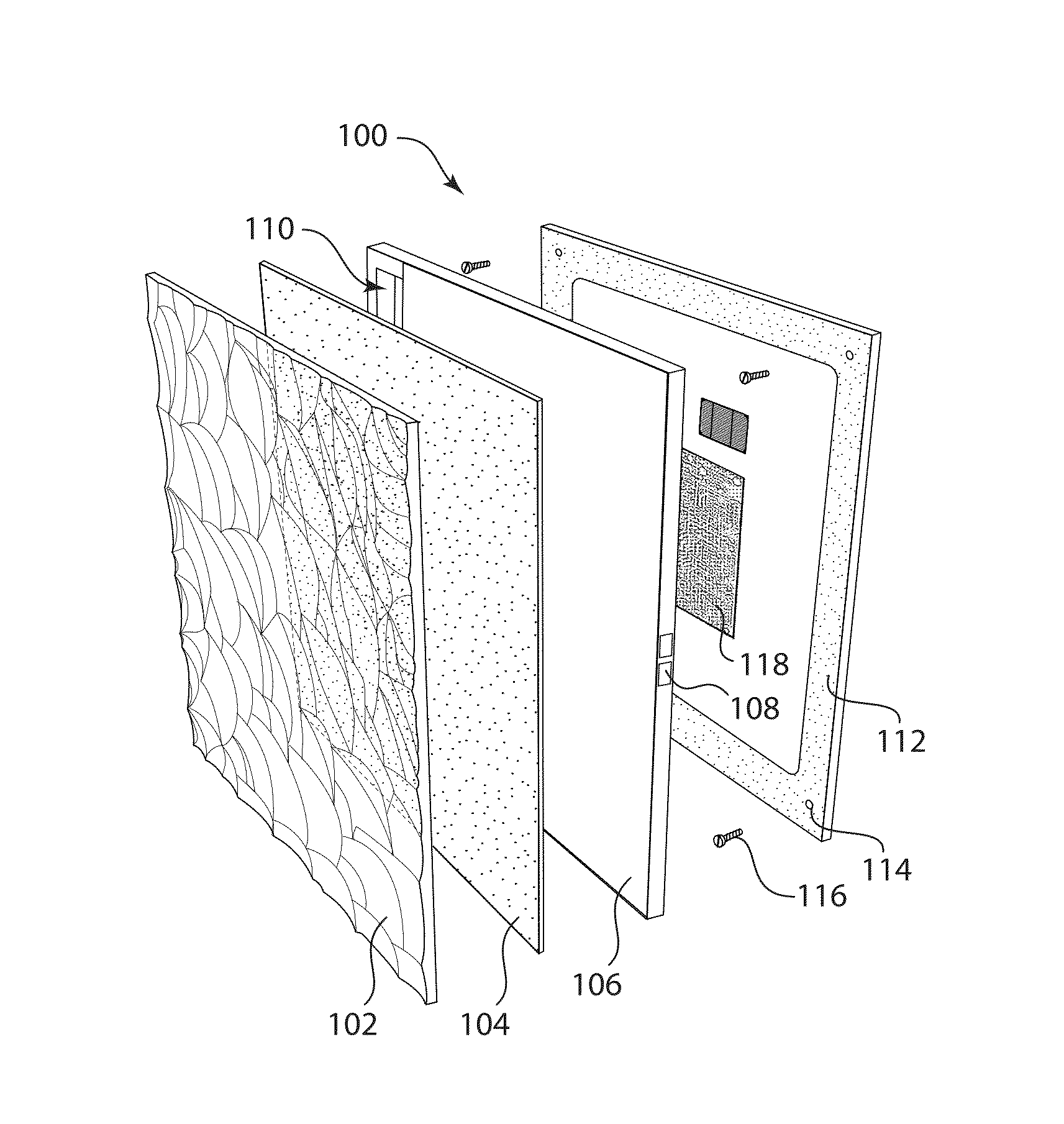
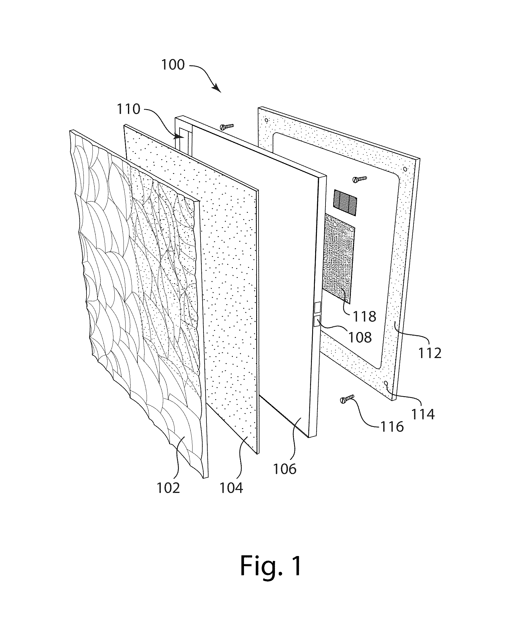
[0063]As indicated above, the present invention provides a variety of devices which make use of electro-optic displays. Although the various types of devices will mainly be described separately below, it will be appreciated that a single physical device may make use of more than one aspect of the present invention; for example, a variable color wall of the present invention could incorporate a variable color marker board of the present invention and / or variable directional signs of the present invention.

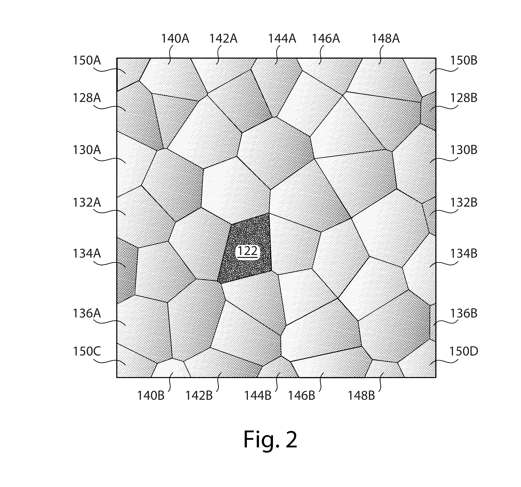
[0064]Variable Color Tile

[0065]As already mentioned, in one aspect this invention provides a tile comprising a light-transmissive (preferably essentially transparent) polymeric layer, a front electrode, an electro-optic layer and a backplane, the polymeric layer being textured to provide a plurality of facets, the tile further comprising a backplane of the direct drive type having segments (pixel electrodes) aligned with the facets on the polymeric layer. The backplane may be in the ...


PUM


Abstract

Electro-optic, especially electrophoretic, displays are used in variety of architectural and furniture applications, including a tile (100) comprising an electro-optic layer (110) capable of changing the color of the file, front and multiple rear electrodes and a light-transmissive polymeric layer (102), the exposed surface of which is textured to provide a plurality of facets inclined to the plane of the tile (100), the rear electrodes being aligned with the facets. A variable color writable board is also provided.

Description

REFERENCE TO RELATED APPLICATIONS[0001]This application claims benefit of provisional Application Ser. No. 62 / 077,154, filed Nov. 7, 2014 and of provisional Application Ser. No. 62 / 099,732, filed Jan. 5, 2015. The entire contents this applications and of all U.S. patents and published and copending applications mentioned below, are herein incorporated by reference.BACKGROUND OF INVENTION[0002]This invention relates to applications of electro-optic displays. More specifically, this invention relates to uses of electro-optic displays, especially but not exclusively, particle-based electrophoretic displays, in architectural, furnishing and similar applications.[0003]The term “electro-optic”, as applied to a material or a display, is used herein in its conventional meaning in the imaging art to refer to a material having first and second display states differing in at least one optical property, the material being changed from its first to its second display state by application of an e...

Claims


Application Information

Patent Timeline
IPC IPC(8): G02F1/167G02F1/1343G02F1/1335G02F1/1333G02F1/1676G02F1/1677
CPCG02F1/167G02F1/13336G02F2001/133562G02F1/1335G02F2001/1676G02F1/134336G02F1/1676E04F13/0871E04F13/18B43L1/12G02F1/1677G02F1/133562
Inventor PAOLINI, JR., RICHARD J.MCCREARY, MICHAEL D.TAUSSIG, CARLAPEN, PAULHARRIS, GEORGE G.SAINIS, SUNIL KRISHNAFILLION, JOSEPH
Owner E INK CORPORATION
Why Eureka
Try Eureka