Aluminum bar and method for producing same

a technology of aluminum bar and aluminum alloy, applied in the field of aluminum bar, can solve problems such as quality degradation

Active Publication Date: 2016-09-22
RESONAC CORP
View PDF7 Cites 7 Cited by
  • Summary
  • Abstract
  • Description
  • Claims
  • Application Information

AI Technical Summary

Benefits of technology

[0010]Some embodiments in this disclosure have been developed in view of the above-mentioned and / or other problems in the related art. The embodiments in this disclosure can significantly improve upon existing methods and / or apparatuses.

Problems solved by technology

Therefore, during the storage, there was a risk that an appearance of soiling and / or an occurrence of corrosion, such as, e.g., oxidation, on the surface of the aluminum bar may cause, resulting in deterioration of the quality.

Method used


Image

  • Aluminum bar and method for producing same
  • Aluminum bar and method for producing same
  • Aluminum bar and method for producing same

Examples


example 1

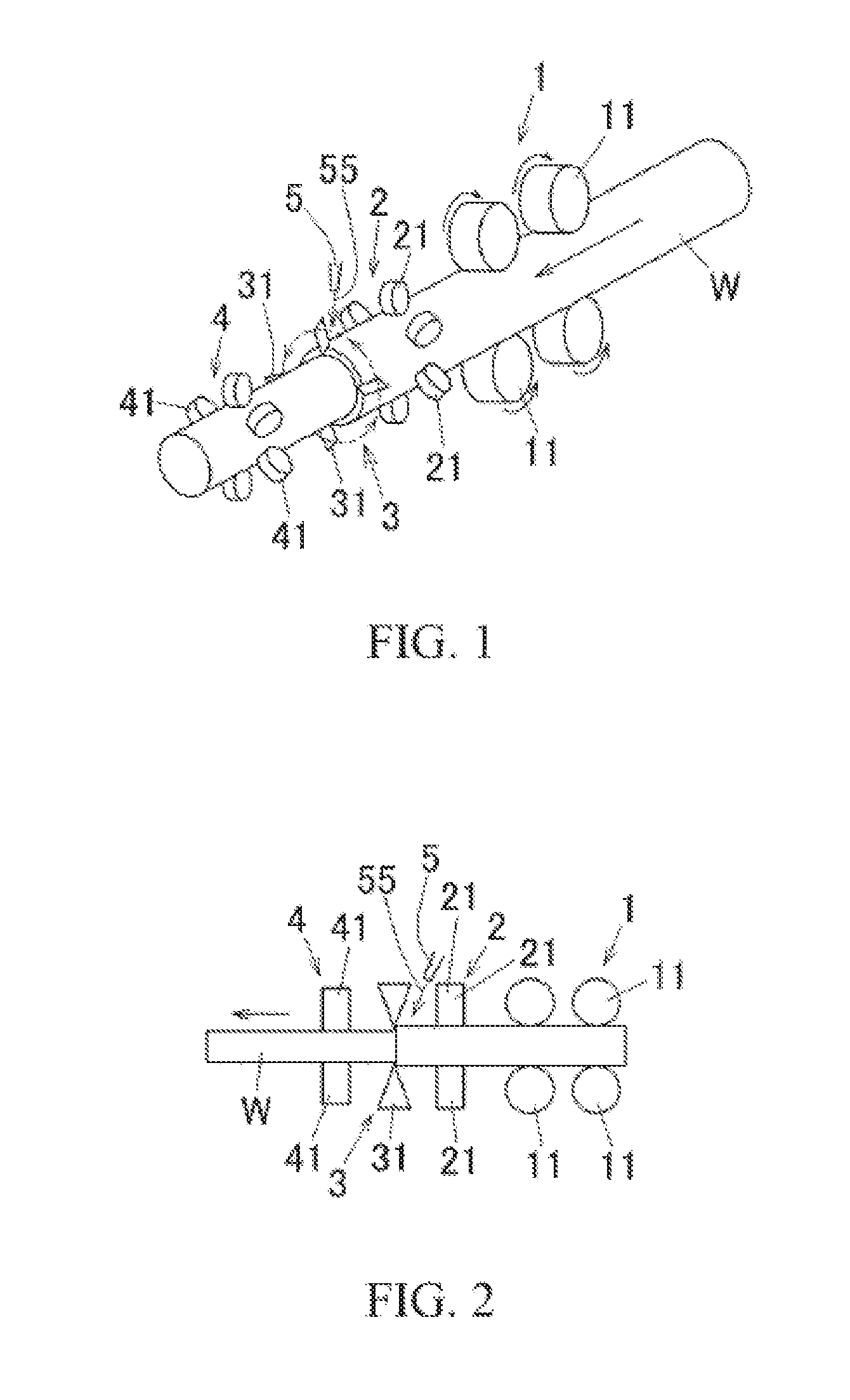
[0101]After subjecting a round bar-shaped continuously cast bar (work) produced by continuously casting 4000 series aluminum alloy to a homogenization treatment, the surface was cut by 3 mm in diameter using a peeling device as shown in FIG. 1 and FIG. 2 to produce an aluminum alloy bar-shaped work having a diameter of 25 mm. As shown in the cutting fluid density item in Table 1, in Example 1, as the cutting fluid (machining fluid) supplied at the time of the peeling step, a cutting fluid in which an undiluted solution of a water-soluble cutting fluid was diluted with water so as to have an oil density (density of the undiluted solution) of 1 mass % was used.

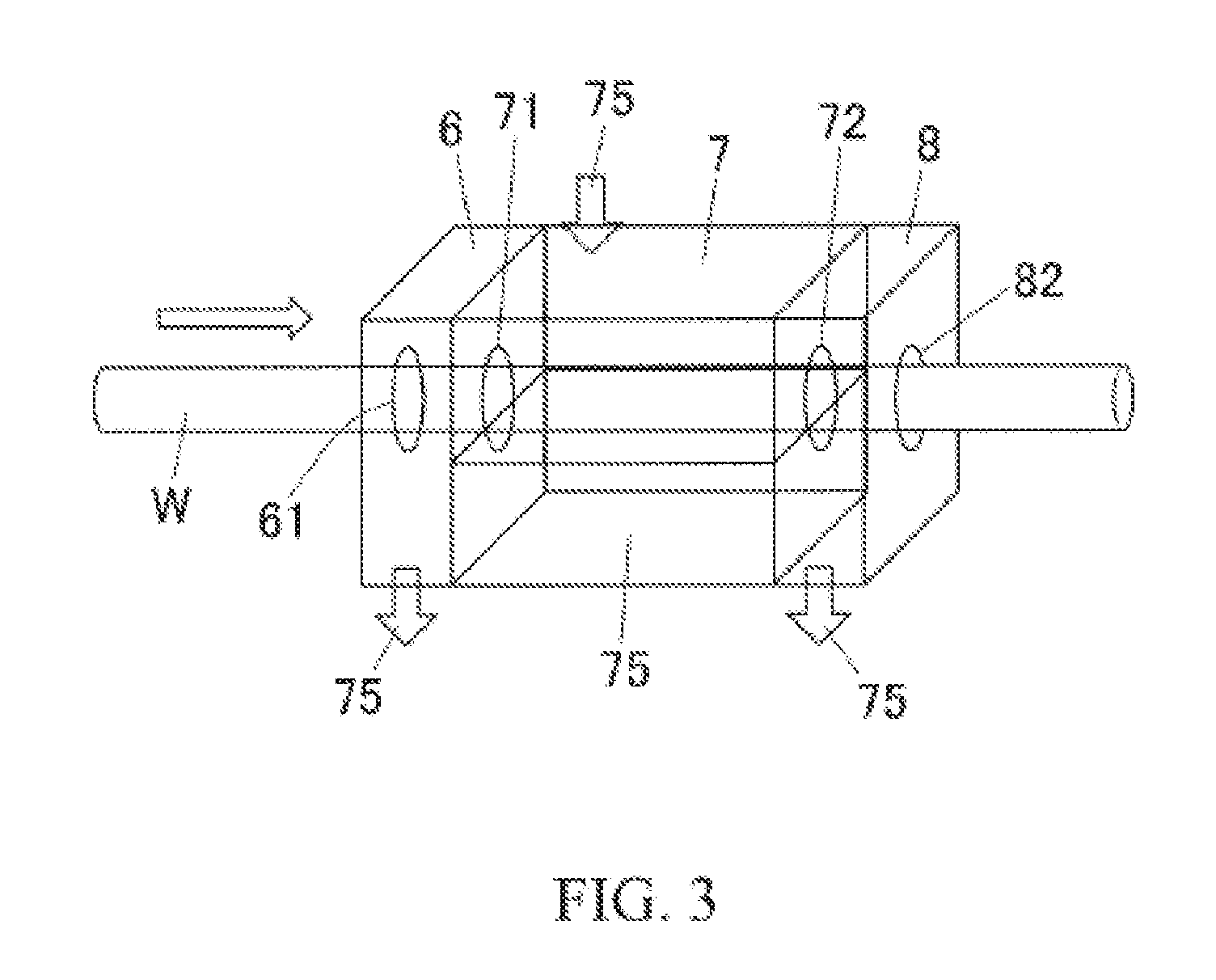
[0102]Next, the work after the peeling step was cleaned using a cleaning device as shown in FIG. 3. At this time, 20° C. industrial water (pH 6.3) was used as the cleaning fluid. In this cleaning step, the work was carried at a carrying speed of 20 m / min. Since the length (width) of the cleaning tank 7 of the cleaning device was...

example 2

[0106]As shown in Table 1, except that a cutting fluid having 7 mass % oil density was used at the time of the peeling step, the sample of Example 2 was produced in the same manner as the aforementioned Example 1.

[0107]Further, the oil remaining amount of the sample of Example 2 measured in the same manner as in Example 1 was 19 μg / cm2.

example 3

[0108]As shown in Table 1, a cleaning method in which 95° C. industrial water was used as a cleaning fluid in the cleaning step was used for a work subjected to the peeling step in the same manner as in Example 1, and the work was further subjected to a curvature correction step using a roll straightening device after the cleaning step. Except for the above, the sample of Example 3 was produced in the same manner as in Example 1. Further, in a curvature correction step using a roll straightening device, the same cutting fluid as the cutting fluid used at the time of the peeling step in Example 3 was supplied to the work.

[0109]Further, the oil remaining amount of the sample of Example 3 measured in the same manner as Example 1 was 7 μg / cm2.


PUM

PropertyMeasurementUnit
pHaaaaaaaaaa
temperatureaaaaaaaaaa

Abstract

A method for producing an aluminum bar includes at least one machining step in which an aluminum bar-shaped work is machined while supplying a machining fluid containing oil to produce a machined aluminum bar-work, and a cleaning step in which the machined aluminum bar-shaped work is cleaned using a cleaning fluid to produce a cleaned machined aluminum bar-shaped work. The cleaning step is performed so that the oil contained in the machining fluid remains on a surface of the cleaned machined aluminum bar-shaped work in a range of 5 μg/cm2 to 20 μg/cm2.

Description

CROSS-REFERENCE TO THE RELATED APPLICATIONS[0001]The present application claims priority to Japanese Patent Application No. 2015-57915 filed on Mar. 20, 2015, the entire disclosure of which is incorporated herein by reference in its entirety.BACKGROUND OF THE INVENTION[0002]1. Technical Field[0003]This disclosure relates to an aluminum bar produced by cleaning an aluminum bar-shaped work machined while supplying a machining fluid and a method for producing the aluminum bar.[0004]In this specification and claims, the term “aluminum (Al)” is used to include the meaning of aluminum (Al) and its alloys.[0005]2. Description of the Related Art[0006]The following description of related art sets forth the inventor's knowledge of related art and certain problems therein and should not be construed as an admission of knowledge in the prior art.[0007]An aluminum bar having a round bar-shape used as a forging blank, etc., is constituted by, for example, a continuously cast bar. Such a continuou...

Claims


Application Information

Patent Timeline
Patent Type & Authority Applications(United States)
IPC IPC(8): B21B45/02B21D3/02B23Q11/10B23D79/12
CPCB21B45/0239B23D79/12B23Q11/1061B21D3/02B21B45/0269B08B3/041B08B3/123B21B3/00B21B2003/001B21C43/00B23B5/12B23B2250/12B08B3/00
Inventor HAYAKAWA, TOMOYA
Owner RESONAC CORP
Why Eureka
Try Eureka