Technical testing method

Active Publication Date: 2016-09-22
SN DETUDE & DE CONSTR DE MOTEURS DAVIATION S N E C M A
View PDF2 Cites 0 Cited by
  • Summary
  • Abstract
  • Description
  • Claims
  • Application Information

AI Technical Summary

Benefits of technology

[0004]The technical test method described in the present disclosure seeks to remedy those drawbacks. In particular, this disclosure seeks to provide a technical test method that makes it possible

Problems solved by technology

Nevertheless, running such a sequence of operating stages of predetermined duration can result in tests presenting an overall dura

Method used


Image

  • Technical testing method
  • Technical testing method
  • Technical testing method

Examples


Example

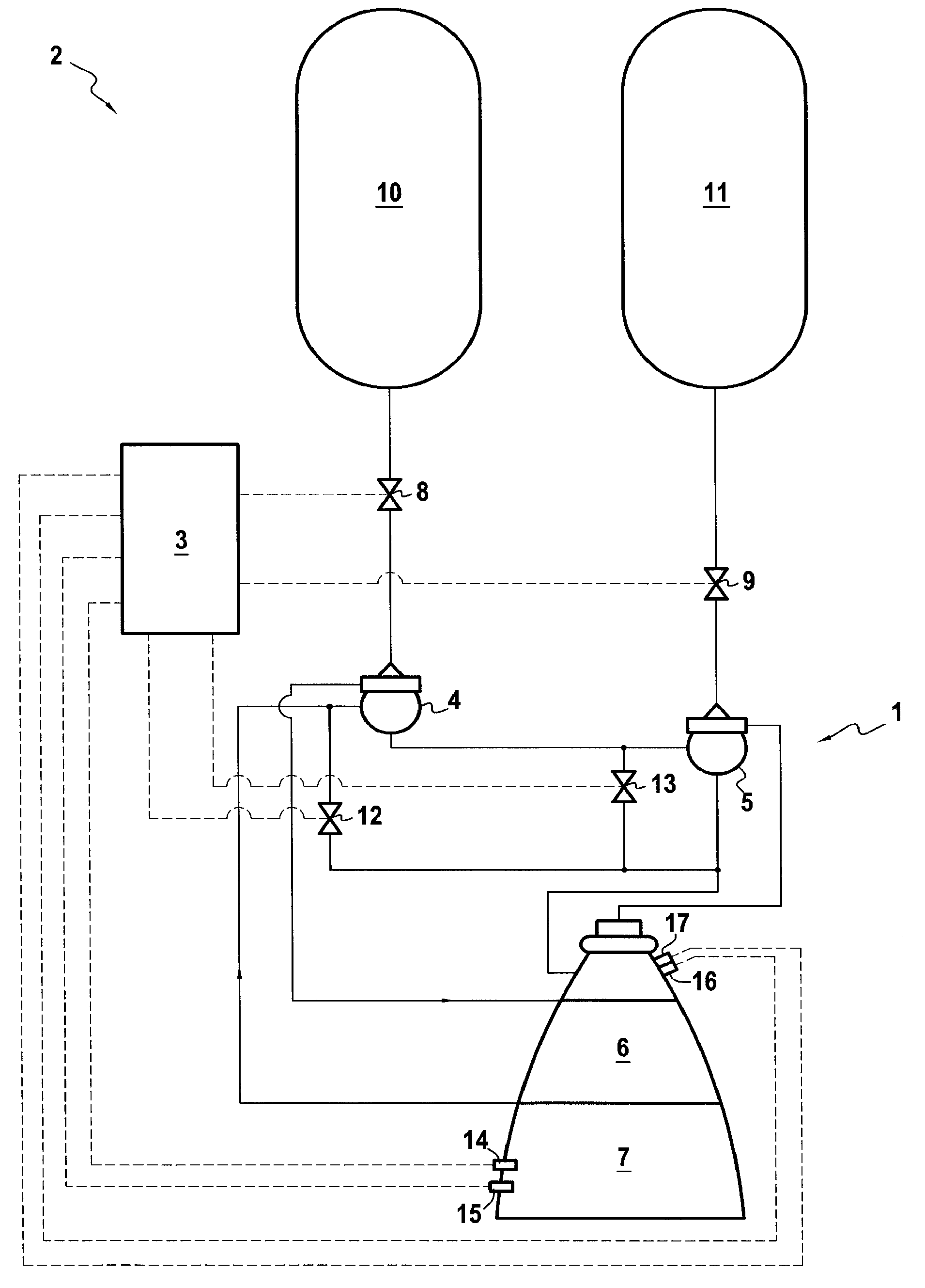
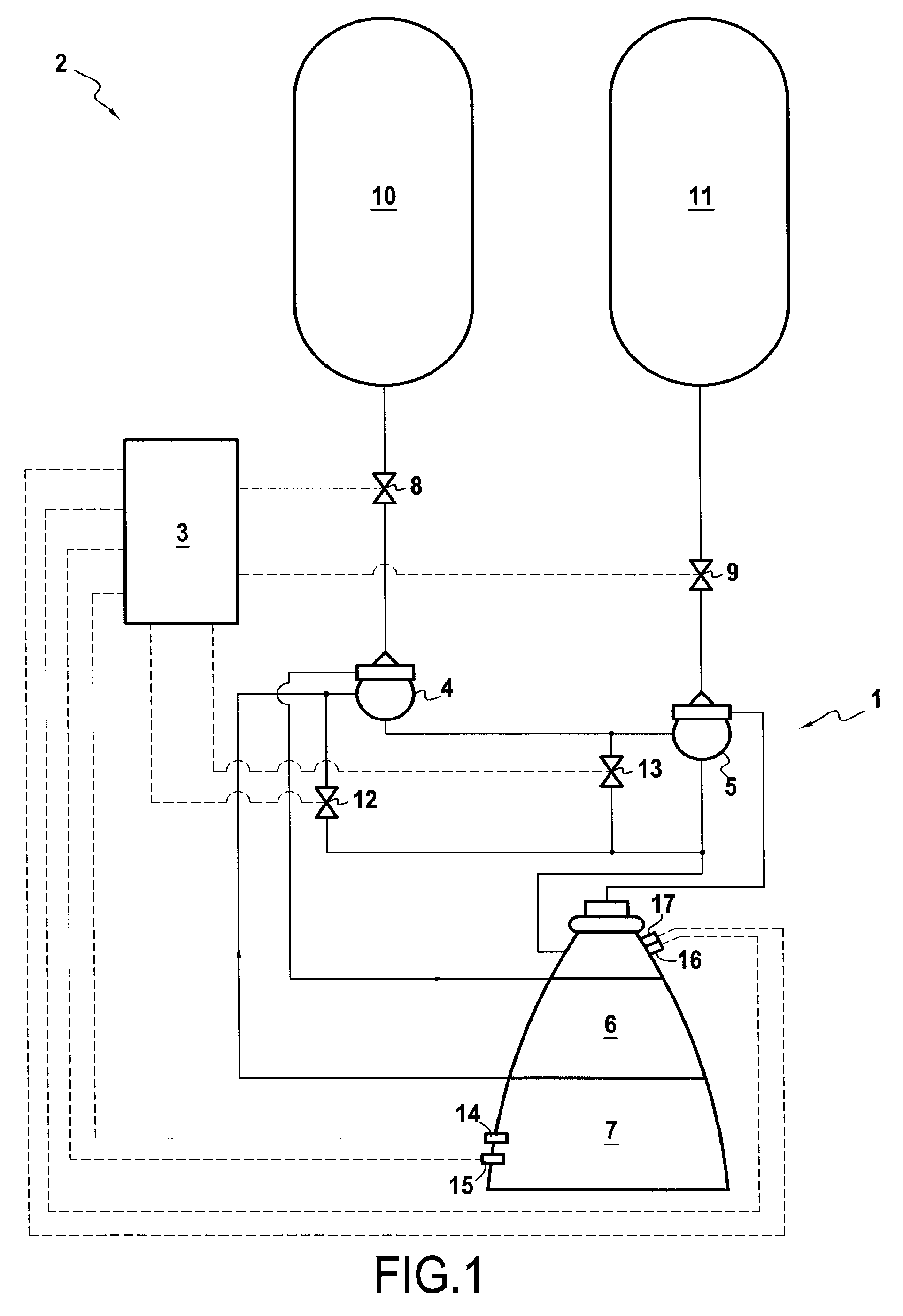
[0018]FIG. 1 shows a liquid-propellant rocket-engine 1 that is fed by turbopumps, the engine being installed on a test bench 2 in which it is connected to an electronic control unit 3 for performing tests using a profile comprising a sequence of a plurality of stages of operation.

[0019]In the embodiment shown, the rocket engine 1 is a rocket engine of the “expansion cycle” type, in which the turbopumps 4 and 5 are actuated by one of the propellants after passing through a regenerative heat exchanger 6 adjacent to the walls of the propulsion chamber 7 of the rocket engine 1. Feed valves 8 and 9 are interposed between the tanks 10 and 11 containing the propellants and the corresponding turbopumps 4 and 5, and bypass valves 12 and 13 enable these turbopumps 4 and 5 to be bypassed at least in part by the propellant heated by the heat exchanger 6. Nevertheless, the invention is not limited in any way to testing such rocket engines, and it may equally well be applied to testing other type...


PUM


Abstract

A field of test methods, and more particularly to a method for testing a device, the method including one operating stage corresponding to a stable value of one operating setpoint for the device and/or for a test bench for testing the device. The operating stage is finalized before a maximum duration threshold if a criterion associated with a set of physical parameters picked up during the operating stage is satisfied and if a confidence level associated with the set of physical parameters reaches at least a predetermined threshold.

Description

BACKGROUND OF THE INVENTION[0001]The present invention relates to a technical test method for testing a device and including operating the device in at least one operating stage that corresponds to a stable value of at least one operating setpoint for the device and / or for a test bench for testing the device.[0002]In the field of technical testing, it is common practice to test devices at a plurality of different operating rates that are to be encountered while the device is in use, with this being for the purpose of characterizing the entire operating envelope of the device as completely as possible. Typically, during testing, this is done by following a sequence comprising a plurality of operating stages, with each operating stage being maintained for a predetermined duration that is considered as being sufficient for guaranteeing the quality of information about operating parameters of the device as obtained over the duration of this stage.[0003]Nevertheless, running such a seque...

Claims


Application Information

Patent Timeline
IPC IPC(8): F02K9/96F04D15/00
CPCF04D15/0088F02K9/96F02K9/00F05D2260/80F05D2260/83G01M15/05
Inventor LE GONIDEC, SERGEREICHSTADT, SEBASTIEN
Owner SN DETUDE & DE CONSTR DE MOTEURS DAVIATION S N E C M A
Why Eureka
Try Eureka