

Drilling System for Rock Drilling
- Summary
- Abstract
- Description
- Claims
- Application Information
AI Technical Summary
Benefits of technology
Problems solved by technology
Method used
Image

Examples
first embodiment
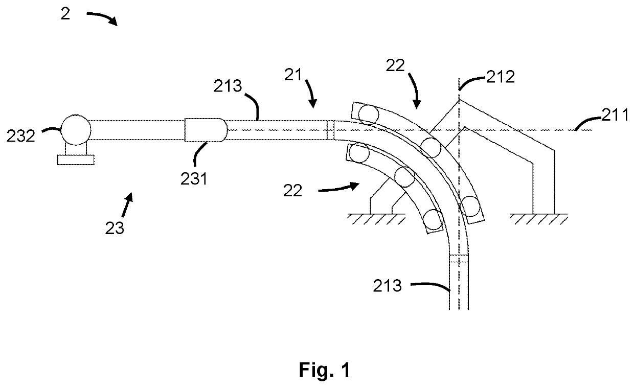
[0035]FIG. 1 illustrates a drilling system 2 for rock drilling with a drill string 21.
[0036]The drill string 21 is shown in its state during operation, being bent between a first direction 211 and a second direction 212. For the purposes of providing a simple example, the first direction 211 and the second direction 212 are arranged with an inclination of 90 degrees. The first direction 211, horizontal, may be imagined as corresponding to the deck of a drill ship 11 and the second direction 212, vertical, may be imagined as corresponding to the direction on which a wellbore is to be drilled.
[0037]An end of the drill string 21 is driven along the first direction 211. There are several ways of accomplishing this actuation. One way is to use two block and tackle systems 23 for driving the drill string 21 back and forth in the first direction 211, in which one of the systems exerts tension on the drill string 21 so as to pull it from the wellbore and another exerts tension on the drill ...
second embodiment
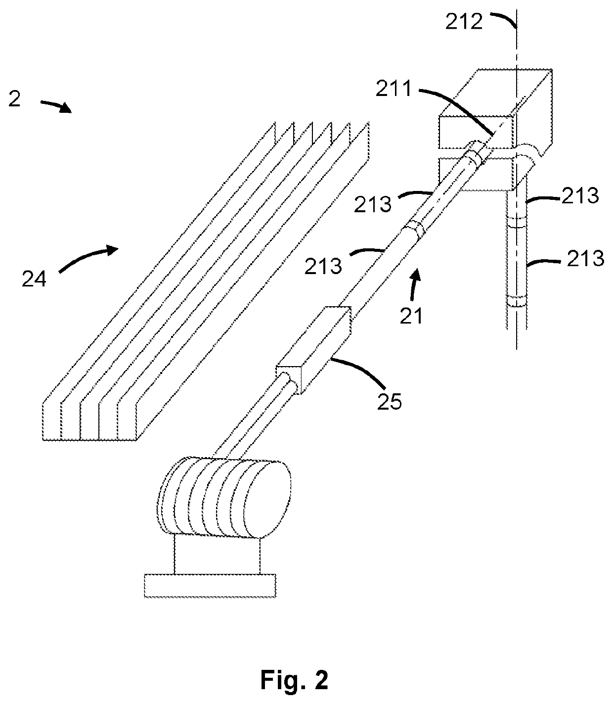
[0043]A drilling operation may be performed by applying a torque to the drill string 21. In this second embodiment, the torque is exerted on the drill string 211 around the first direction 211, which then transmits the torque, through the drill string 21, to the second direction 212. In order to apply this torque around the first direction 211, a topdrive 25 is provided at an end of the drill string 21 in the first direction 211.
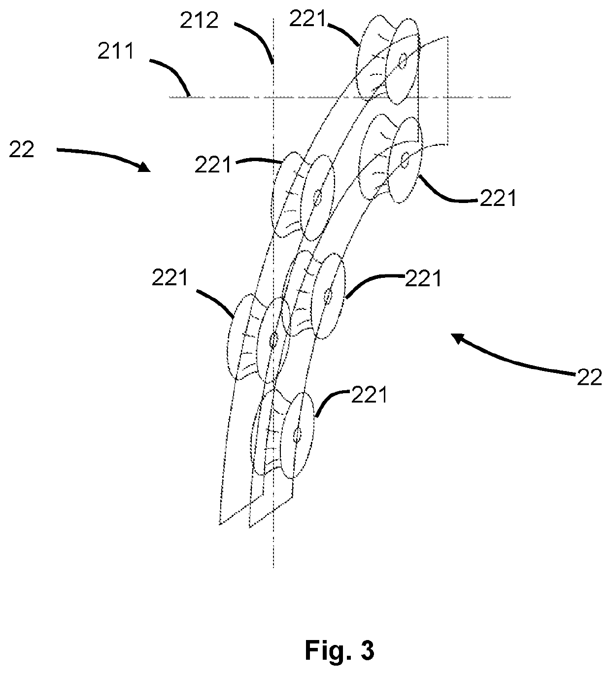
[0044]FIG. 3 illustrates an embodiment of two conveyor devices 22 for guiding and bending the drill string 21.
[0045]Each of the conveyor devices 22 include three rollers 221 supported by a curved frame. Each roller 221 is of the “bow tie” type, which provides a better contact with the drill string 21. Particularly, these rollers 221 allow to bend the drill string 21 between the first direction 211 and the second direction 212 while it moves back and forth, or even if it turns, for example while drilling.
[0046]FIG. 4 illustrates a drill ship 11 including an e...
PUM
 Abstract
Description
Claims
Application Information