
Displaying attenuating audio signal level in delayed fashion

a technology of delay and display control, applied in the direction of signal processing, instruments, computing, etc., can solve the problem of not being able to effect level display reflecting, and achieve the effect of easy-to-recognize level display

Inactive Publication Date: 2016-09-22
YAMAHA CORP
View PDF4 Cites 2 Cited by
  • Summary
  • Abstract
  • Description
  • Claims
  • Application Information

AI Technical Summary

Benefits of technology

The present invention provides a display control apparatus for a mixing console that can adjust the display delay time of the level meter based on the attenuation characteristics of different audio signals. This allows for a better understanding of the level of the audio signals and ensures that the display responds appropriately when the audio signal is attenuated. Additionally, the display control apparatus can automatically set the display delay time for each type of supply source of audio signals, making it easier for users to quickly visually recognize the level of the audio signals. Overall, the invention improves the usability and ease-of-use of the mixing console.

Problems solved by technology

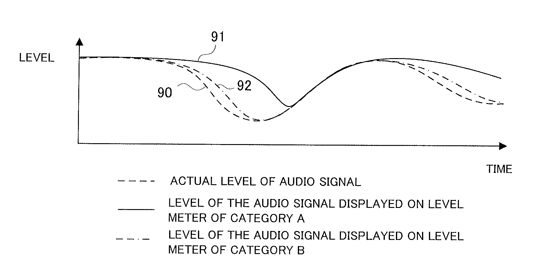
However, with the conventionally-known mixers, where a response speed to level variation of an audio signal is set identically among the level meters (i.e., all of the level meters are set uniformly at the same response speed to audio signal level variation), it is not possible to effect a level display reflecting differences between attenuation speeds corresponding to musical instrument types of the individual channels.

Method used


Image

  • Displaying attenuating audio signal level in delayed fashion
  • Displaying attenuating audio signal level in delayed fashion
  • Displaying attenuating audio signal level in delayed fashion

Examples


Embodiment Construction

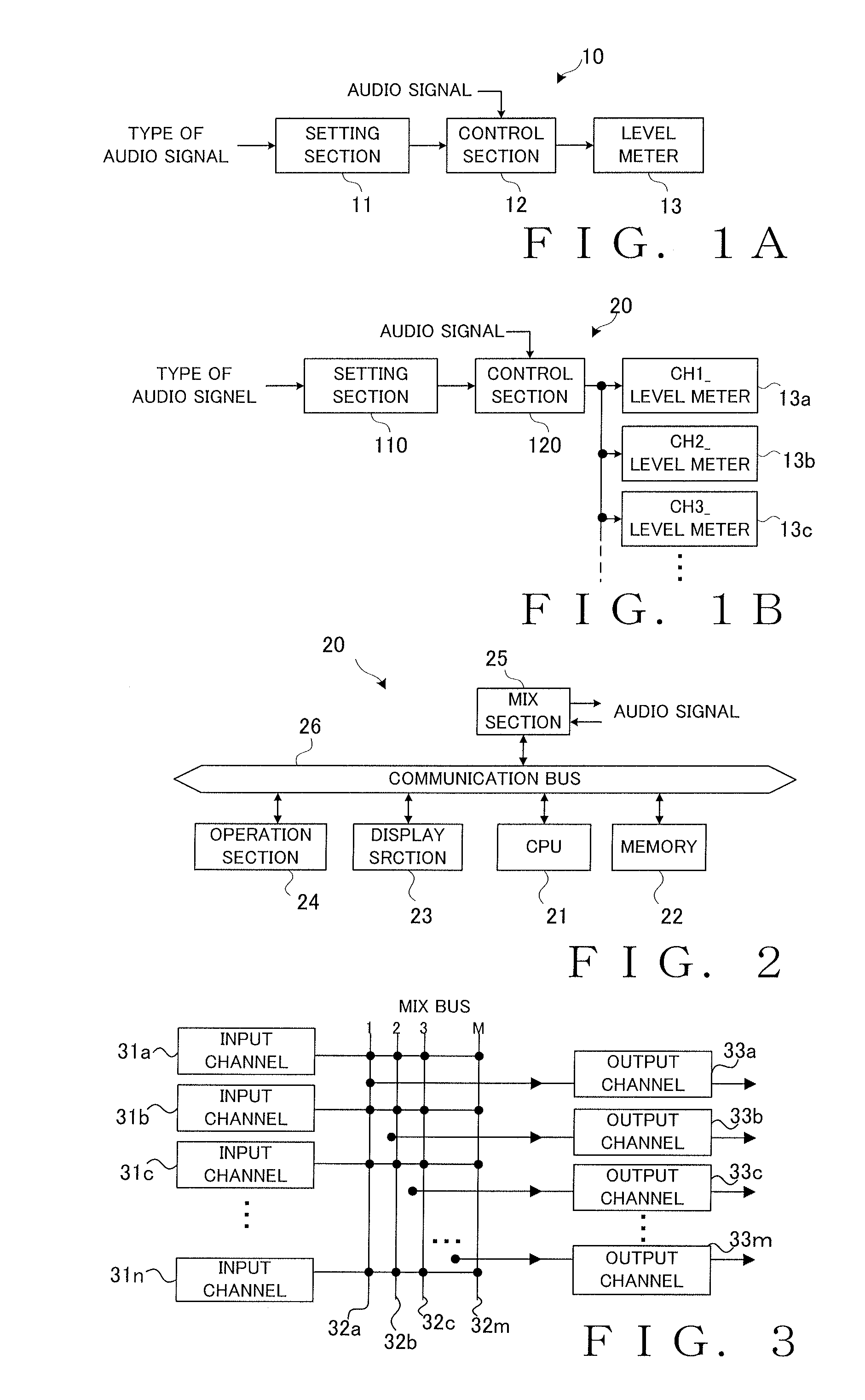
[0026]FIG. 1A is a block diagram showing an example construction of a display control apparatus 10 according to an embodiment of the present invention. The display control apparatus 10 shown in FIG. 1A is constructed to control a level meter 13 that displays a level of an audio signal. The level meter 13 employed here is in the form of LEDs, an LCD, an analog meter or the like and constructed to visibly display level variation of an audio signal in a continuous manner. In the case where the level meter 13 is in the form of a, LED array comprising a plurality of LED elements arranged in a generally shape or a generally band-shaped image displayed on an LCD, for example, an illumination width of the level meter 13 increases or decreases in response to level variation of an audio signal so that the level variation of the audio signal is displayed in a continuous manner. In the case where the level meter is in the form of an analog meter, level variation of an audio signal is displayed ...


PUM


Abstract

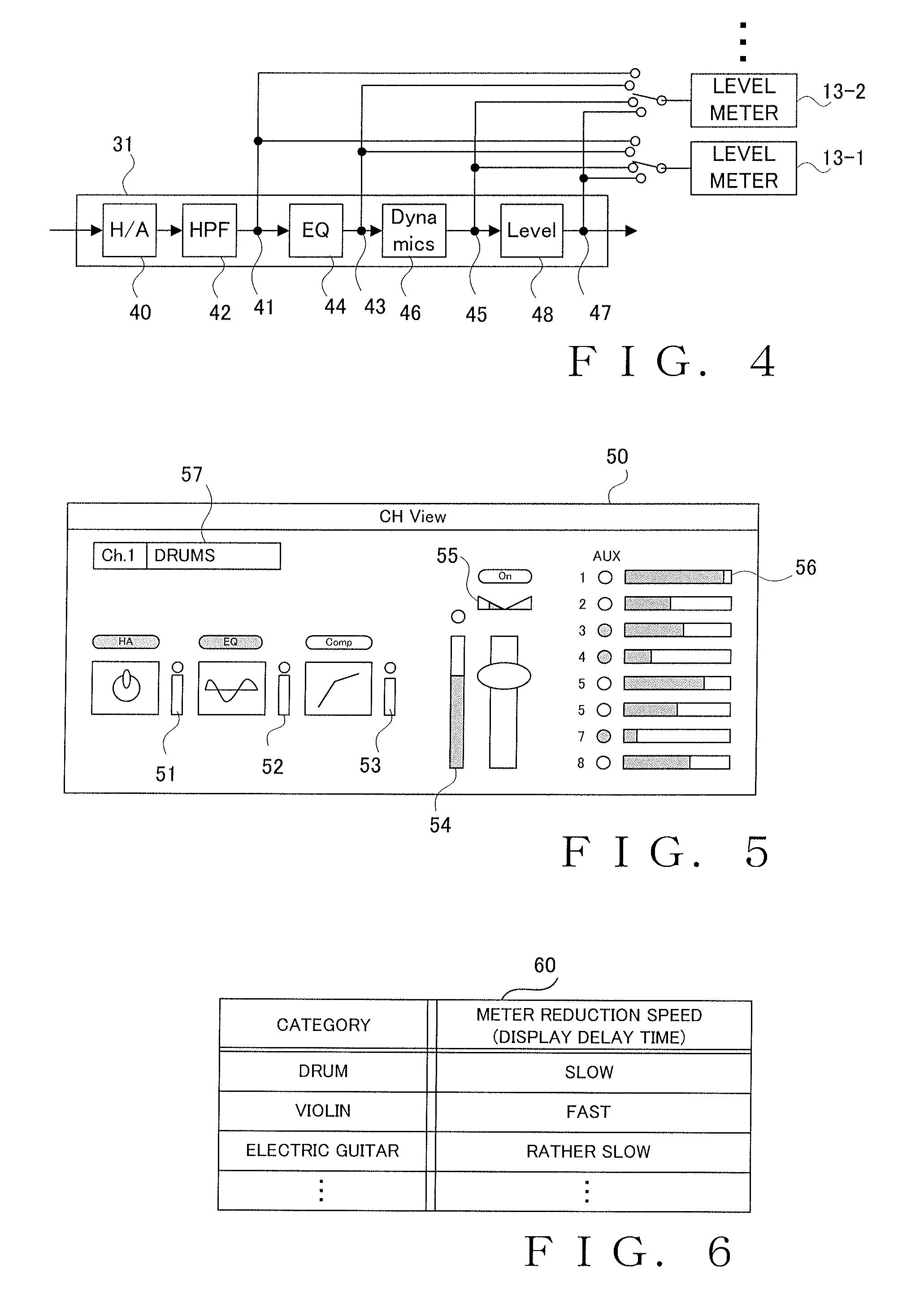
A disclosed apparatus includes: a setting section that variably sets a display delay time relative to attenuation variation of the level of the audio signal; and a control section that controls, in accordance with the display delay time set by the setting section, an attenuation style of the level of the audio signal to be displayed on the level meter. For example, per different type of supply source of the audio signal, display delay time information predefining a display delay time suitable for the type is stored in a memory. Based on the display delay time information stored in the storage section, the setting section sets a display delay time corresponding to the type of the supply source of the audio signal.

Description

BACKGROUND[0001]The present invention relates to display control apparatus for controlling a level meter that displays a level of an audio signal and more particularly relates, for example, to a display control apparatus suitable for level meters provided on a mixing console that performs signal processing on audio signals of a plurality of channels.[0002]In the fields of audio equipment such as audio recorders and audio amplifiers and video equipment such as video cameras and video reproduction (player) devices, it has heretofore been known to provide a level meter for monitoring a level of an audio signal input to the equipment. Among examples of such a level meter is one capable of not only displaying a level of an audio signal but also holding a peak value of the audio signal level for a given time period to display the thus-held peak value simultaneously with the audio signal level. Japanese Patent Application Laid-open Publication No. HEI-05-157578 (hereinafter referred to as ...

Claims


Application Information

Patent Timeline
IPC IPC(8): G06F3/16G06F3/0481
CPCG06F3/0481G06F3/165H04R29/008H04R2420/01H04R2430/01
Inventor KAMIYA, SHUNICHITERADA, KOTARO
Owner YAMAHA CORP
Learn More