Variable hardness actuator
a variable hardness actuator and actuator technology, applied in the field of variable hardness actuators, can solve the problems of deformation of the tube, the tube stays in place, and the difficulty of further inserting the tube deep into the lumen
- Summary
- Abstract
- Description
- Claims
- Application Information
AI Technical Summary
Benefits of technology
Problems solved by technology
Method used
Image
Examples
first embodiment
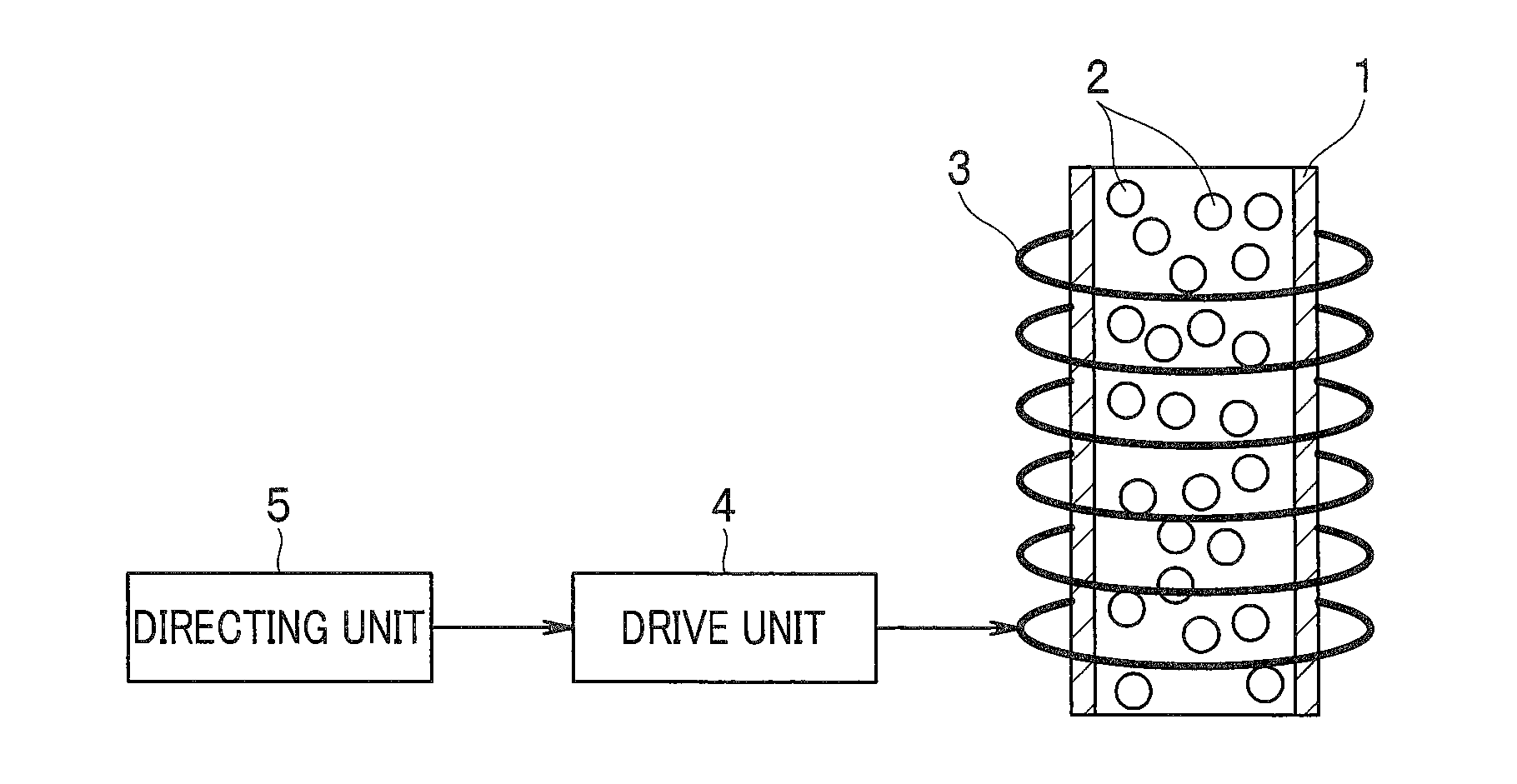
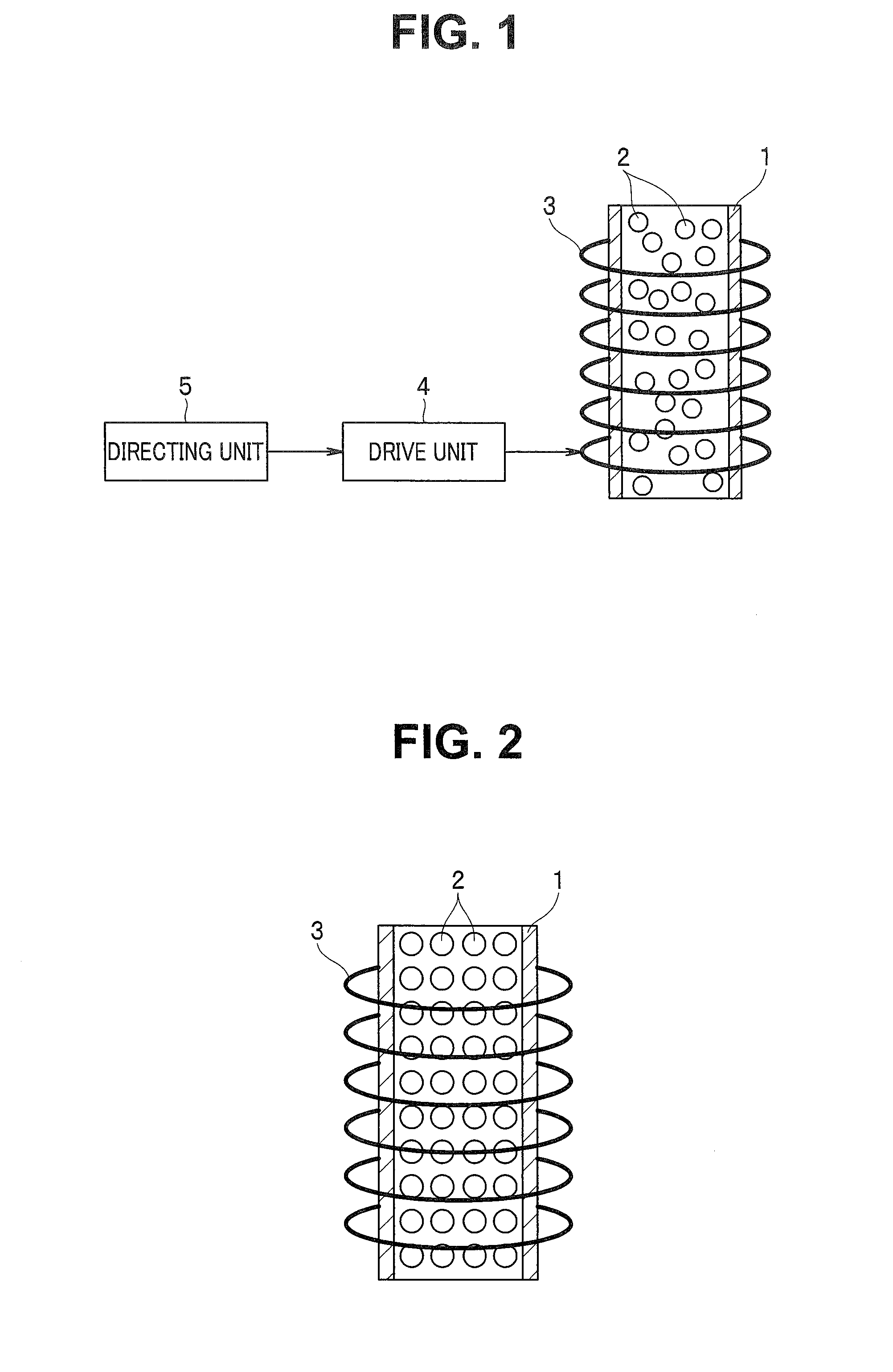
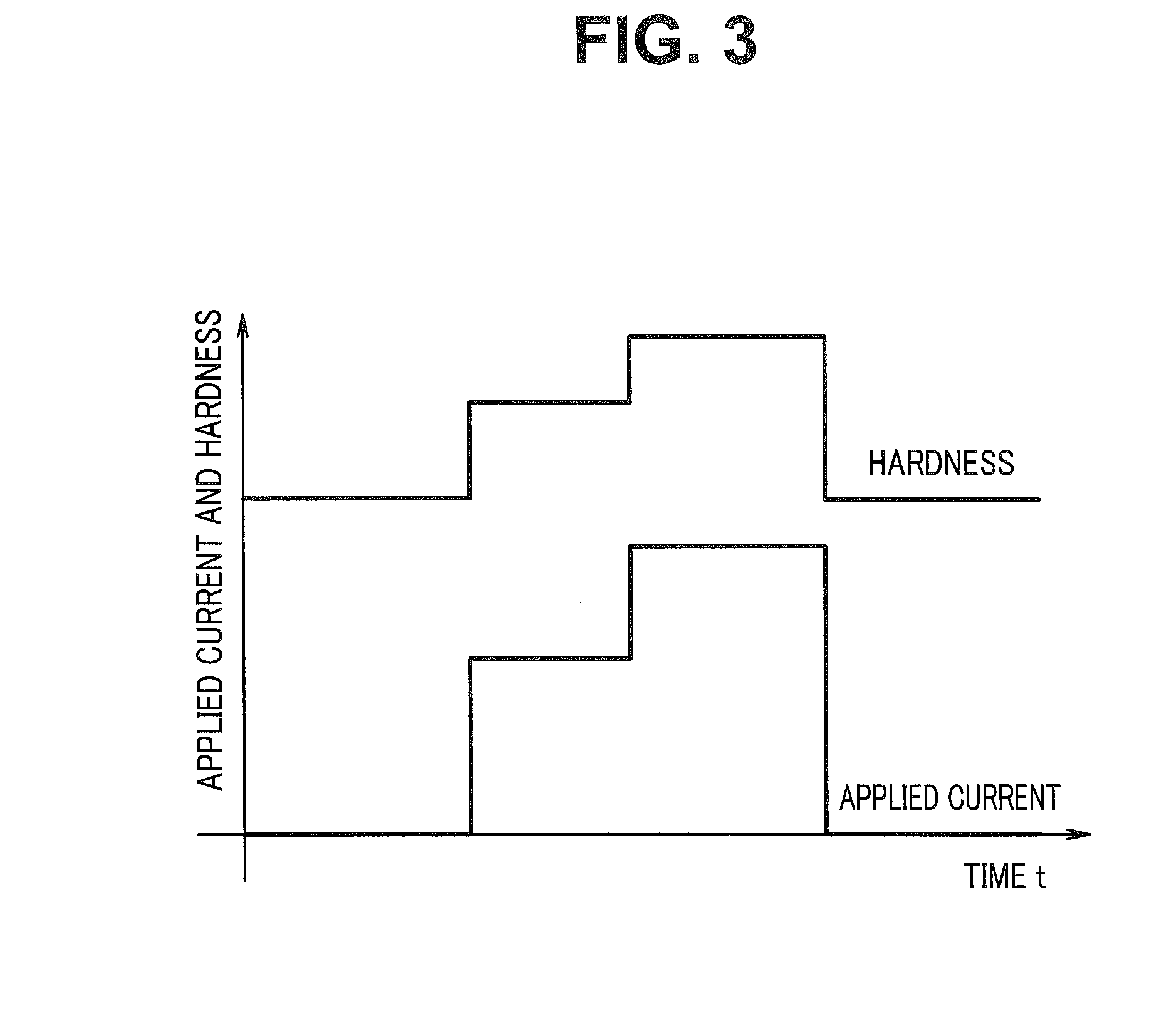
[0020]FIGS. 1 to 4 show a first embodiment of the present invention, where FIG. 1 is a diagram showing a configuration of a variable hardness actuator.
[0021]As shown in FIG. 1, the variable hardness actuator includes a tubular member 1, magnetic powder 2, a coil 3, a drive unit 4, and a directing unit 5.
[0022]The tubular member 1 is a tube-shaped member provided with flexibility and configured to flex when a bending force is applied. Note that it is assumed below that the tubular member 1 has (but is not limited to) a cylindrical shape, in particular. Then, an equal amount of bending is available when a bending force is applied in any direction perpendicular to an axial direction (radial direction of the cylinder) as long as a magnitude of the force is the same.
[0023]The magnetic powder 2 is powdered magnetic bodies, and the tubular member 1 is filled with plural particles of the magnetic powder 2. Note that FIG. 1 shows the variable hardness actuator in a non-hardened state and the...
second embodiment
[0047]FIGS. 5 and 6 show a second embodiment of the present invention, where FIG. 5 is a diagram showing a state of a variable hardness actuator when not hardened and FIG. 6 is a diagram showing a state of the variable hardness actuator when hardened.
[0048]In the second embodiment, description of parts similar to those of the first embodiment described above will be omitted as appropriate by taking measures such as denoting the parts with the same reference numerals as the corresponding parts and mainly differences from the first embodiment will only be described.
[0049]Whereas in the first embodiment described above, the magnetic bodies are made up of magnetic powder 2, in the present embodiment, the magnetic bodies are made up of magnetic wire rods 2A.
[0050]That is, the magnetic bodies according to the present embodiment are bendable magnetic wire rods 2A. A plurality of the magnetic wire rods 2A are placed along the axial direction of the tubular member 1 and filled into the tubul...
third embodiment
[0054]FIGS. 7 to 9 show a third embodiment of the present invention, where FIG. 7 is a diagram showing a state of a variable hardness actuator when not hardened, FIG. 8 is a diagram showing a state of the variable hardness actuator when hardened, and FIG. 9 is a diagram showing a configuration of a variable hardness actuator according to a modification.
[0055]In the third embodiment, description of parts similar to those of the first and second embodiments described above will be omitted as appropriate by taking measures such as denoting the parts with the same reference numerals as the corresponding parts and mainly differences from the first and second embodiments will only be described.
[0056]The present embodiment uses columnar magnetic bodies 2B or spherical magnetic bodies 2C as magnetic bodies.
[0057]To begin with, the magnetic bodies shown in FIGS. 7 and 8 are columnar magnetic bodies 2B with an outside diameter a little smaller than an inside diameter of the cylindrical tubula...
PUM
 Abstract
Description
Claims
Application Information
 - R&D
- Intellectual Property
- Life Sciences
- Materials
- Tech Scout
- Unparalleled Data Quality
- Higher Quality Content
- 60% Fewer Hallucinations
Browse by: Latest US Patents, China's latest patents, Technical Efficacy Thesaurus, Application Domain, Technology Topic, Popular Technical Reports.
© 2025 PatSnap. All rights reserved.Legal|Privacy policy|Modern Slavery Act Transparency Statement|Sitemap|About US| Contact US: help@patsnap.com


