
Speaker and edge structure thereof

a technology of speaker and edge structure, applied in the field of speaker, can solve the problems of increased cost, increased cost, and increased cost, and achieve the effect of inhibiting excessive vibration, excessive amplitude of vibration to be controlled, and inhibiting excessive vibration

Inactive Publication Date: 2016-09-22
DB TECHNOLOGY
View PDF0 Cites 9 Cited by
  • Summary
  • Abstract
  • Description
  • Claims
  • Application Information

AI Technical Summary

Benefits of technology

The present invention provides an edge structure with a control part that allows for a thinner and less expensive speaker without compromising sound quality. By shaping the edge with a thin outer peripheral end and inner peripheral end, the inventors found that an excessive vibration of the diaphragm can be prevented. This control part can effectively inhibit vibration of the diaphragm and allows for a thinner speaker without the need for a damper. The speaker produced using this edge structure is cost-effective and performs well.

Problems solved by technology

Further as mentioned above, the damper must be produced by subjecting the prepreg substrate produced by impregnating a cotton yarn or the like with a resin to molding in a mold, which leads to increase in cost, and therefore, further cost reduction is demanded.
On the other hand, if a damper is not used, there is no control part for inhibiting an excessive vibration of a diaphragm, which causes a problem that control of a diaphragm is not performed sufficiently and sound quality is lowered.
In this case, if the edge is thickened outward on the both surfaces thereof, an elastic force of the edge itself decreases, and the vibration of the diaphragm is inhibited excessively.

Method used


Image

  • Speaker and edge structure thereof
  • Speaker and edge structure thereof
  • Speaker and edge structure thereof

Examples


Embodiment Construction

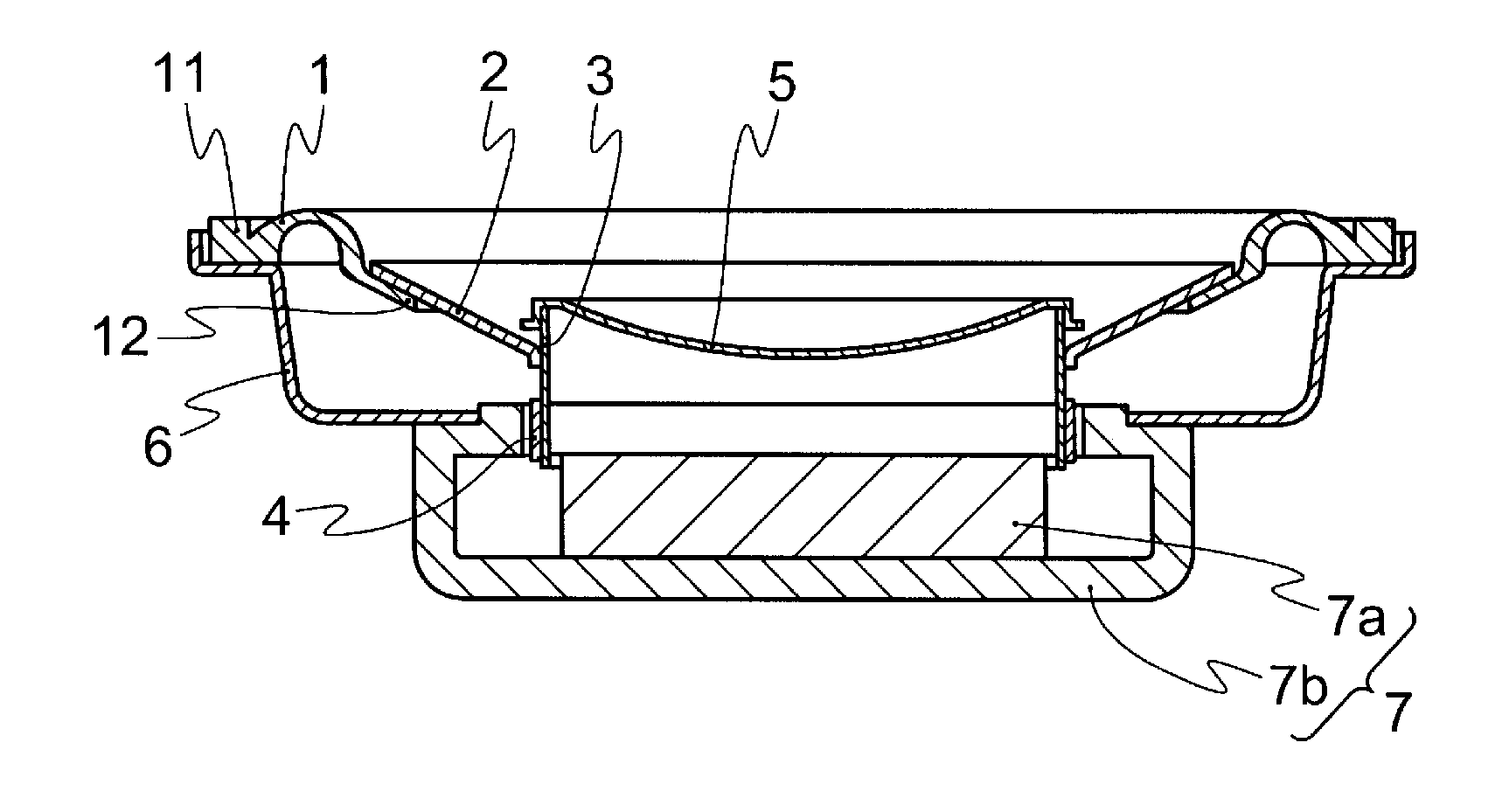
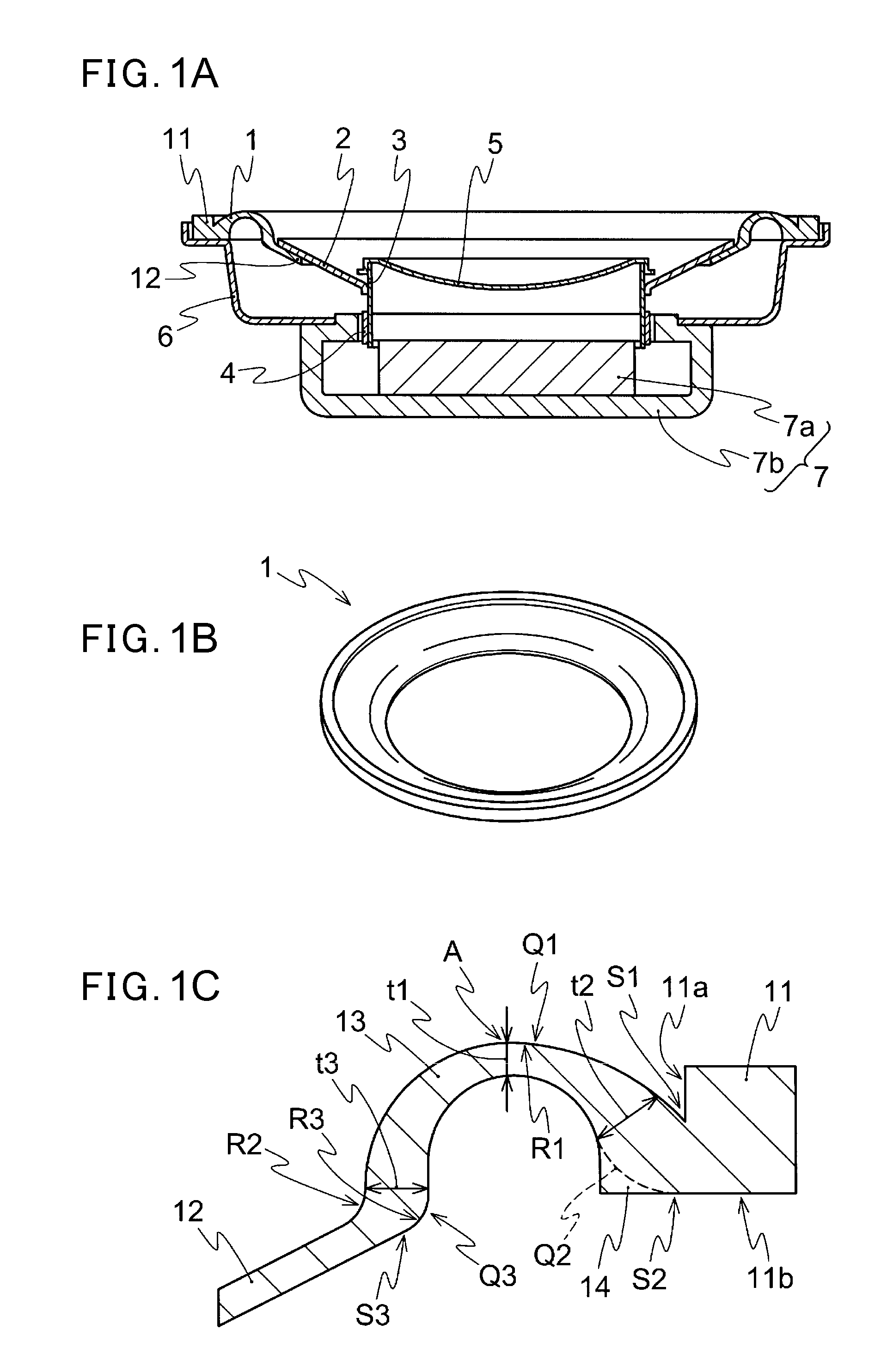
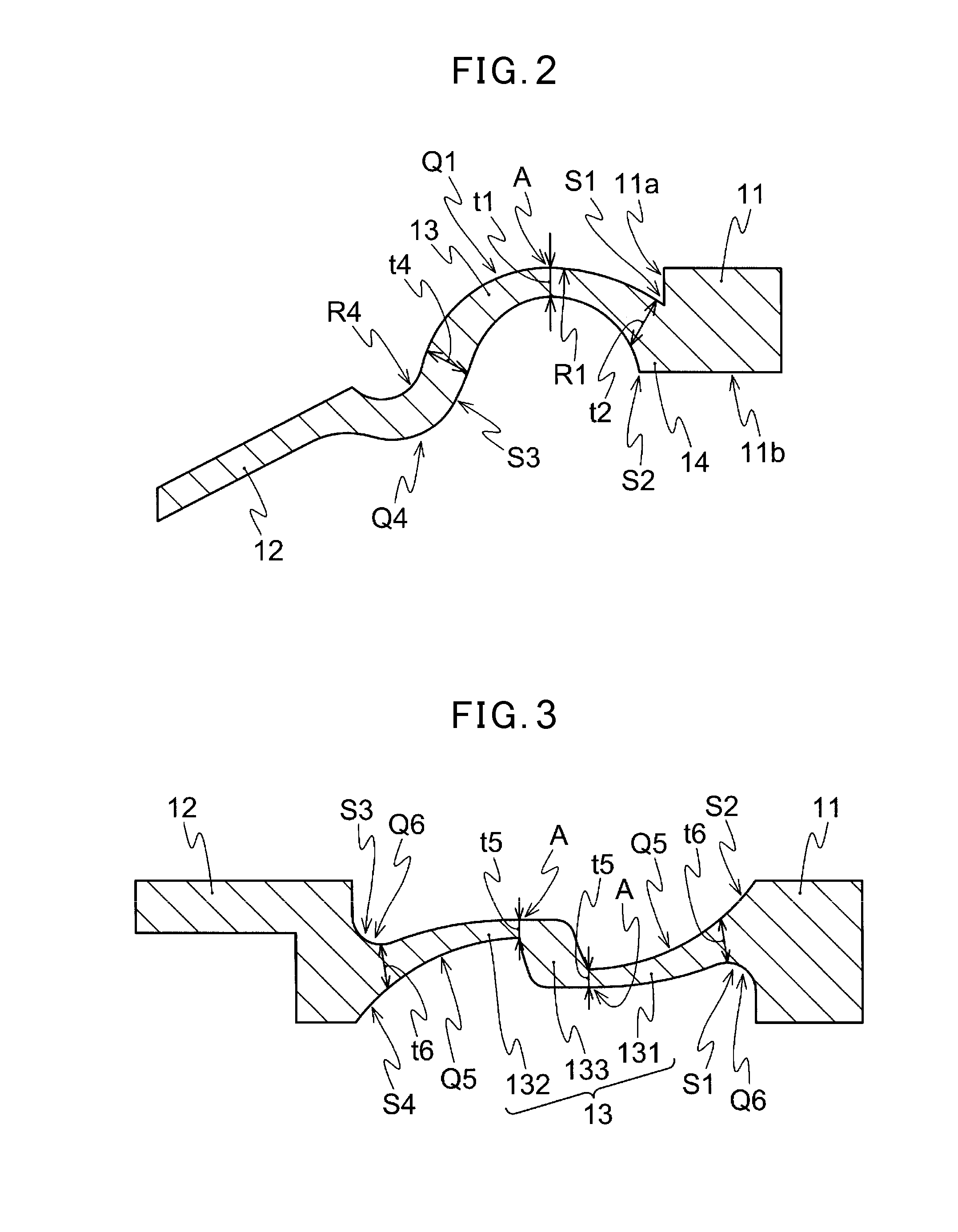
[0031]Next, the speaker of the presently disclosed embodiment and its edge are explained by referring to the drawings. The edge of the speaker of the presently disclosed embodiment, as shown in a perspective view and a cross-sectional view of one aspect thereof in FIGS. 1B and 1C, respectively, is formed in the sheet-like and ring shape and comprises an outer fixing part 11 formed on an outer peripheral part for fixing to the frame (supporting member) 6, an inner fixing part 12 formed on an inner peripheral part for fixing a diaphragm 2, and a sheet-like part 13 connecting the outer fixing part 11 and the inner fixing part 12. On both surfaces of the sheet-like part 13 at least at the boundary portion of the sheet-like part 13 and the outer fixing part 11, the respective convex portions for controlling the bending are formed, thereby forming control parts S1, S2 for controlling vibration of the diaphragm 2. Further, the sheet-like part 13 also has a thinnest part A in its cross-sect...


PUM


Abstract

An edge for a speaker making it possible to decrease a thickness of the speaker and achieve cost reduction by using no damper without lowering a sound quality is provided. The edge of a speaker is in a sheet-like and ring form and includes an outer fixing part formed on its outer peripheral part for fixing the edge to the frame (supporting member), an inner fixing part formed on its inner peripheral part for fixing the edge to the diaphragm, and a sheet-like part lying between the inner fixing part and the outer fixing part (connecting the inner fixing part and the outer fixing part). The respective convex portions are formed at least on both surfaces of the sheet-like part at the boundary portion of the sheet-like part and the outer fixing part, thereby forming the control parts for controlling the vibration of the diaphragm.

Description

CROSS-REFERENCE TO RELATED APPLICATIONS[0001]This application is the National Stage of International Application No. PCT / JP2013 / 082786 having International Filing Date, 6 Dec. 2013, which designated the United States of America, and which claims priority from, and the benefit of, Japanese Application No. 2013-121929, filed on 10 Jun. 2013, the disclosures of which are incorporated herein by reference in their entireties.BACKGROUND[0002]1. Field[0003]The presently disclosed embodiment relates to a speaker including a speaker having a drive mechanism and a passive radiator type speaker, and an edge structure thereof, in particular to an edge having a structure enabling an excessive amplitude of vibration of a diaphragm to be inhibited only with the edge by providing a control part on the edge without using a damper, and to a speaker using the edge.[0004]2. Brief Description of Related Developments[0005]Conventional speakers have, for example, a structure as shown in FIG. 6A. Namely, i...

Claims


Application Information

Patent Timeline
Patent Type & Authority Applications(United States)
IPC IPC(8): H04R7/18H04R9/02H04R1/28H04R9/06
CPCH04R7/18H04R9/06H04R2307/207H04R1/2834H04R9/025H04R7/20
Inventor SHIKIMACHI, BUNJIROIMADA, HAJIME
Owner DB TECHNOLOGY
Learn More