Four-wheel drive vehicle and control device for four-wheel drive vehicle
a four-wheel drive, control device technology, applied in the direction of mechanical actuated clutches, vehicle sub-unit features, gearing, etc., can solve the problems of high speed rotation of electric motors, noise and vibration, driver and occupant(s) of four-wheel drive vehicles, and reduce driving stability. , the effect of reducing noise and vibration
- Summary
- Abstract
- Description
- Claims
- Application Information
AI Technical Summary
Benefits of technology
Problems solved by technology
Method used
Image
Examples
first embodiment
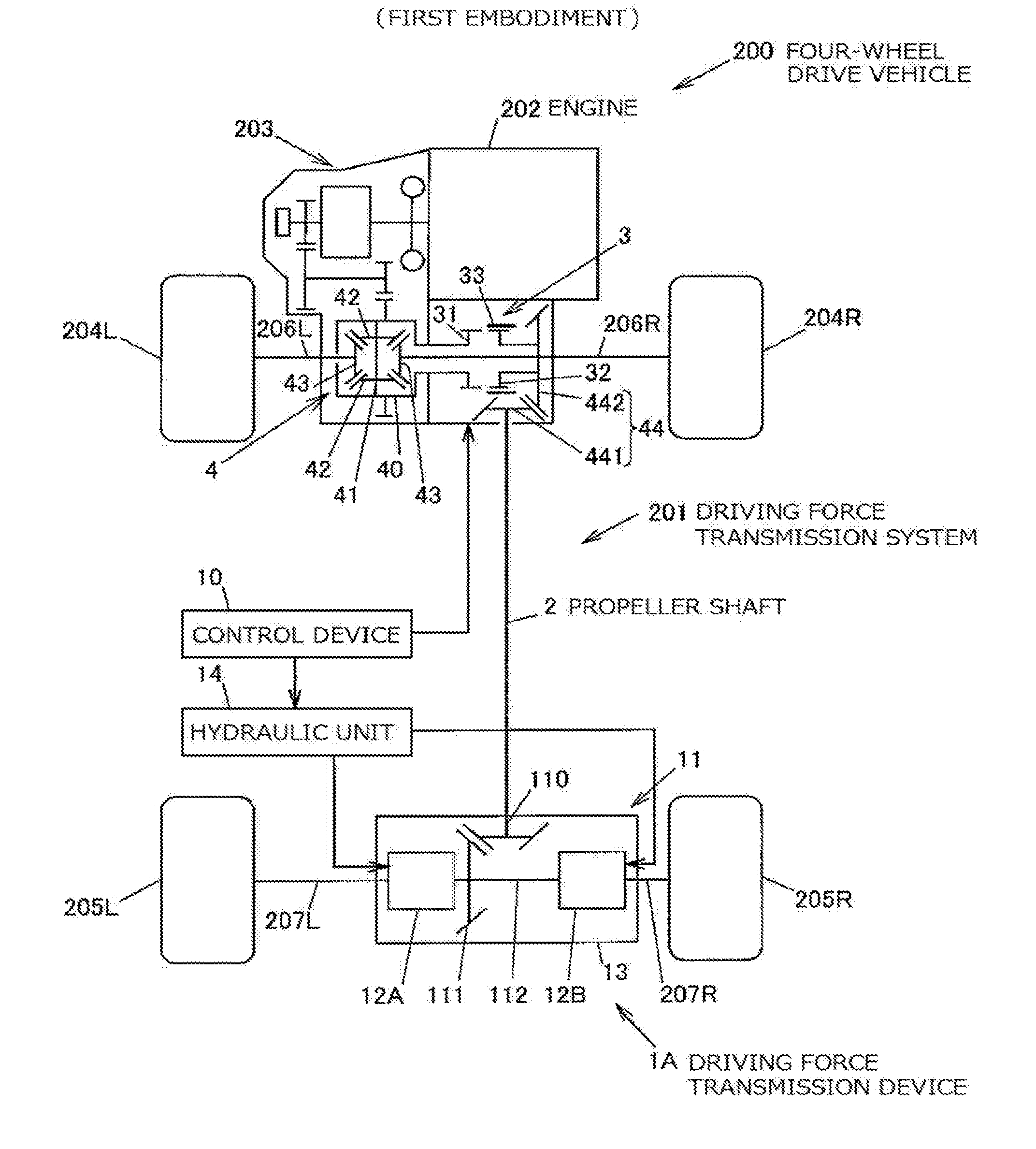
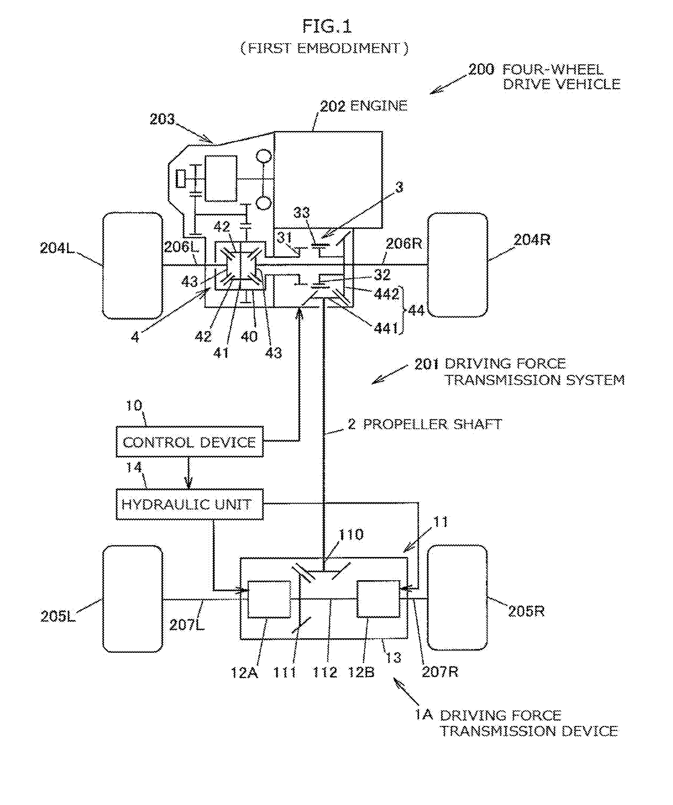
[0028]Embodiments of the present invention will be described with reference to the accompanying drawings. FIG. 1 is a diagram schematically showing the configuration of a four-wheel drive vehicle according to the present invention.
[0029]The general configuration of the four-wheel drive vehicle will be described. A four-wheel drive vehicle 200 includes an engine 202 serving as a driving source for generating a driving force for driving the vehicle, a transmission 203, a pair of right and left front wheels 204R, 204L serving as main drive wheels, a pair of right and left rear wheels 205R, 205L serving as auxiliary drive wheels, a driving force transmission system 201, and a control device 10. The driving force transmission system 201 can transmit the driving force of the engine 202 to the front wheels 204R, 204L and the rear wheels 205R, 205L. The control device 10 controls the driving force transmission system 201. In the present embodiment, the letters “L” and “R” in the reference c...
second embodiment
[0099]FIG. 8 is a diagram schematically showing the configuration of the four-wheel drive vehicle 200 according to the
[0100]In FIG. 8, the same members as those described in the first embodiment are denoted with the same reference characters as those of FIG. 1, and description thereof will be omitted.
[0101]The four-wheel drive vehicle 200 according to the present embodiment has a rear differential 9 and a driving force transmission device 1B instead of the driving force transmission device 1A of the first embodiment. The rear differential 9 has a differential case 90, a pinion shaft 91, a pair of pinion gears 92, a pair of side gears 93, and a ring gear 94. The pinion shaft 91 rotates together with the differential case 90. The pair of pinion gears 92 are supported by the pinion shaft 91. The pair of side gears 93 mesh with the pair of pinion gears 92 such that the axes of the pair of side gears 93 extend perpendicularly to those of the pair of pinion gears 92. The ring gear 94 is f...
PUM
 Abstract
Description
Claims
Application Information
 - R&D
- Intellectual Property
- Life Sciences
- Materials
- Tech Scout
- Unparalleled Data Quality
- Higher Quality Content
- 60% Fewer Hallucinations
Browse by: Latest US Patents, China's latest patents, Technical Efficacy Thesaurus, Application Domain, Technology Topic, Popular Technical Reports.
© 2025 PatSnap. All rights reserved.Legal|Privacy policy|Modern Slavery Act Transparency Statement|Sitemap|About US| Contact US: help@patsnap.com


