Self-adjusting supporting head

a self-adjusting, supporting head technology, applied in the direction of lifting frames, lifting devices, railway components, etc., can solve the problems of inability to avoid the size error of four steel plates welded on the side beam of vehicles, poor precision and heavy workload, and inconvenient adjustment of a variety of supporting heads at the same tim

Active Publication Date: 2016-09-29
CRRC QINGDAO SIFANG ROLLING STOCK RES INST
View PDF0 Cites 3 Cited by
  • Summary
  • Abstract
  • Description
  • Claims
  • Application Information

AI Technical Summary

Benefits of technology

[0014]Compared with prior art, this invention can achieve the following beneficial effects:
[0015](1) The bottom part of the stop block is probed into the interior of the cylindrical hole, and a stop block movement gap is provided between the bottom part of the stop block and the cylindrical hole, which is used to restrict the floating load-bearing block to swing within the stop block movement gap only, instead of a large-angle swing, ensure that only a small angle adjustment is made between the floating load-bearing block and the floating load-bearing block mounting base, and guarantee that the adjustment between them is moderate;
[0016](2) The floating load-bearing block is mounted on the floating load-bearing block mounting base through disc springs and disc spring guide posts. When there is no load of the disc spring, a load-bearing block floating gap is formed between the lower surface of the floating load-bearing block and upper surface of the floating load-bearing block mounting base through the spring action of the disc spring, making the floating load-bearing block connected with but not contacted with the floating load-bearing block mounting base, so that the floating load-bearing block can swing on the floating load-bearing block mounting base freely;
[0017](3) The supporting head is provided with a floating load-bearing adjusting device, comprising a floating load-bearing block, a floating load-bearing mounting base and a floating connector. The floating load-bearing block is in spherical fit with the floating load-bearing block mounting base. The floating load-bearing block can swing in random directions above the floating load-bearing block mounting base according to the specific state of a steel plate in contact with the floating load-bearing block. When the height of a number of steel plates welded on the vehicle side beam is inconsistent, the floating load-bearing block can automatically align according to the steel plates through the spherical fit structure, and achieve full contact between the upper surface of the floating load-bearing block and the plurality of steel plates, ensure that the vehicle side beam is uniformly stressed, without damage to the vehicle.

Problems solved by technology

The basic type supporting head has a simple structure, and it is inconvenient to adjust a variety of supporting heads simultaneously.
It can achieve adjustment conveniently and display the weight of the whole vehicle, but when adjusting a variety of supporting heads, it is necessary to adjust them one by one repeatedly, with poor precision and heavy workload.
During lifting maintenance operation, the size error of four steel plates welded on the side beam of vehicles can not be avoided, with a certain height difference between the four steel plates, thus, they can not be on the same plane.
For the above supporting heads with weighing functions and basic type supporting heads, it is inconvenient to adjust a variety of supporting heads simultaneously, and when the load-bearing surface of the existing supporting head and the lifting column are an integral structure, the upper surface of supporting head can not form a state of line contact or point contact with four steel plates on the side beam completely when lifting, which easily causes damage to the vehicle.

Method used


Image

  • Self-adjusting supporting head
  • Self-adjusting supporting head
  • Self-adjusting supporting head

Examples


example 1

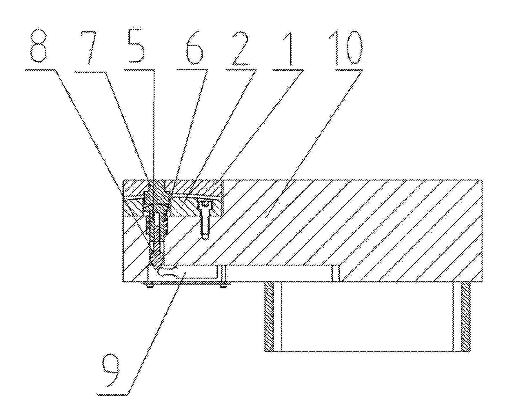
[0025]A self-adjusting supporting head comprises a vehicle body lifting column 10 and a load-bearing detection device arranged on the vehicle body lifting column 10; the load-bearing detection device comprises a spring supporting plate 5, a spring 6, a limiting switch tip 8, a load limiting switch 9 and a floating load-bearing adjusting device. The floating load-bearing adjusting device is mounted at the top of the vehicle body lifting column 10 and the spring supporting plate 5 is arranged below the floating load-bearing adjusting device, the spring 6 is mounted on the periphery of the spring supporting plate 5, the upper end of the limiting switch tip 8 is connected to the spring supporting plate 5 and on the low end side is provided with a load limiting switch 9.

[0026]The floating load-bearing adjusting device comprises a floating load-bearing block 1, a floating load-bearing block mounting base 2 and a floating connector. The floating load-bearing block 1 is mounted on the upper...

example 2

[0034]The structure and composition of the self-adjusting supporting head in example 2 are basically the same as those in example 1, with the distinguishing characteristics as follows: the stop block 7 is of an inverted T-shaped structure, and the top end of the inverted T structure is fixedly connected with the floating load-bearing block 1, and the bottom of the inverted T-shaped structure is of a planar structure. The planar structure of the bottom end of the inverted T-shaped structure is in a point contact with the spherical structure at the top of the spherical top end, to make concentrated load-bearing force exerted on the T-shaped structure by the stop block 7, facilitating to press the spring 6 by the spring supporting plate 5 and making the limiting switch tip 8 to move downwards.

[0035]Technicians skilled in the art should understand that the drawings are only for a preferred embodiment, and the structures and compositions in the drawings are not necessary for the implemen...


PUM


Abstract

A self-adjusting supporting head comprises a vehicle body lifting column (10) and a load-bearing detection device arranged on the vehicle body lifting column (10). The load-bearing detection device comprises a spring supporting plate (5), a spring (6), a limiting switch tip (8), a load limiting switch (9) and a floating load-bearing adjusting device. The floating load-bearing adjusting device comprises a floating load-bearing block (1), a floating load-bearing block mounting base (2) and a floating connector. The floating load-bearing block is in spherical fit with the floating load-bearing block mounting base.

Description

CROSS-REFERENCE TO RELATED APPLICATIONS[0001]This application is a continuation of International application No. PCT / CN2014 / 088891 filed on Oct. 20, 2014, entitled SELF-ADJUSTING SUPPORTING HEAD, which claims the priority benefit of Chinese patent application No. 201410405841.0, filed on Aug. 18, 2014. The contents of the above-mentioned patent applications are incorporated by reference herein in their entirety and made a part of this specification.FIELD OF THE INVENTION[0002]The present invention relates to a kind of maintenance operation equipment used in non-disintegrated rack car of motor train unit and urban rail vehicles, in particular, to a kind of self-adjusting supporting head of vehicle body lifting unit of pit-type lifting jack used in train vehicle body.BACKGROUND OF THE INVENTION[0003]When a pit-type lifting jack is used in maintenance operation of non-disintegrated rack car of motor train unit and urban rail vehicles, it is necessary to lift the vehicle to a certain he...

Claims


Application Information

Patent Timeline
Patent Type & Authority Applications(United States)
IPC IPC(8): B66F7/28B61F99/00
CPCB66F7/28B66F2700/12B61F99/00B61K13/00B66F17/00B61K5/00
Inventor WANG, MINGHAIDING, HUIWANG, YONGZHAO, XIAOLEI
Owner CRRC QINGDAO SIFANG ROLLING STOCK RES INST
Why Eureka
Try Eureka