
Classroom retrofit barriers

a technology for retrofitting barriers and classrooms, applied in the field of ballistic barriers, can solve the problems of difficult installation for a single maintenance person, exorbitant inconvenient installation, so as to reduce the cost of shielding protection provided, the effect of adding too much weight to the door and thin ballistic skin

Inactive Publication Date: 2016-09-29
DAW TECH
View PDF0 Cites 5 Cited by
  • Summary
  • Abstract
  • Description
  • Claims
  • Application Information

AI Technical Summary

Benefits of technology

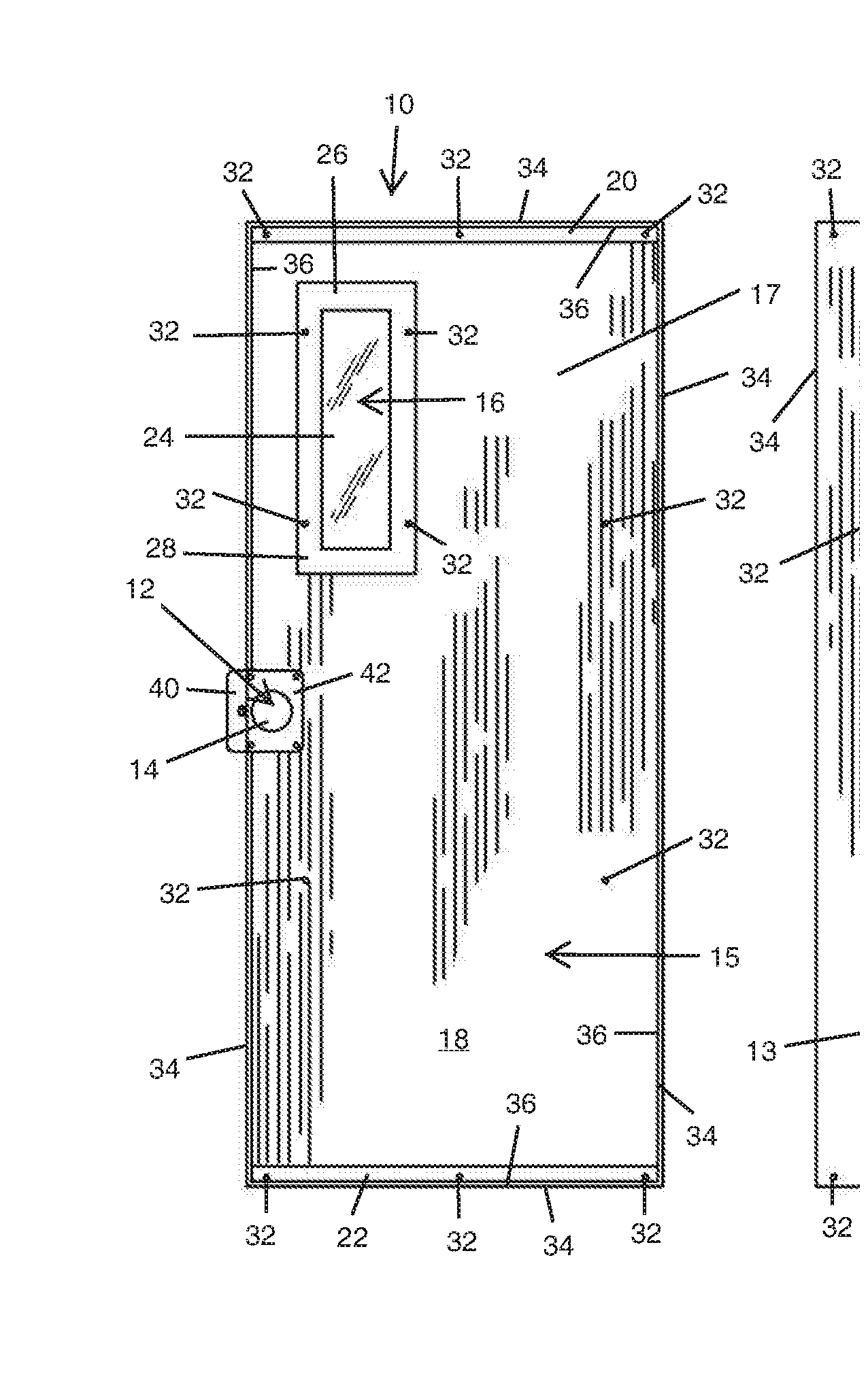
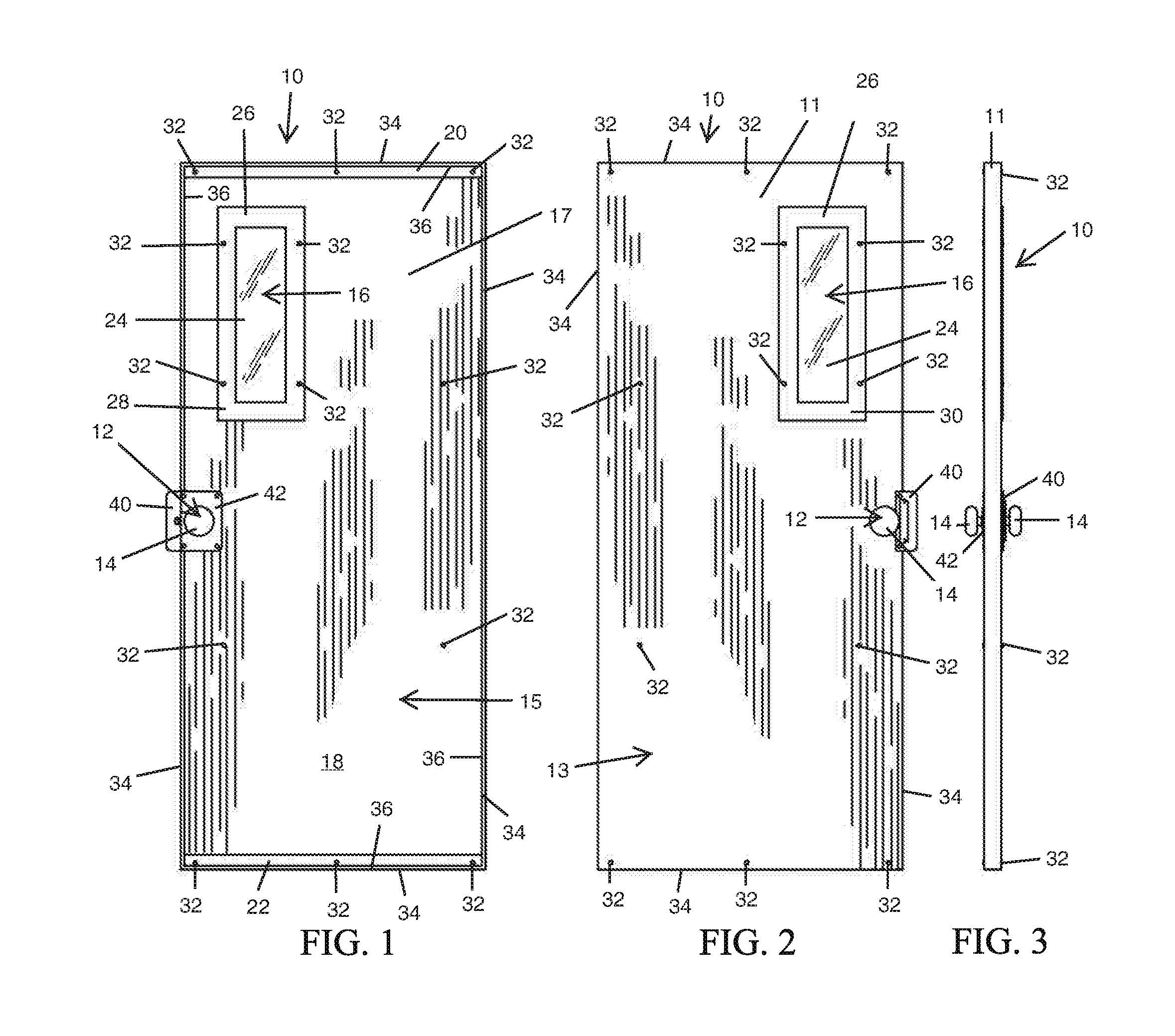
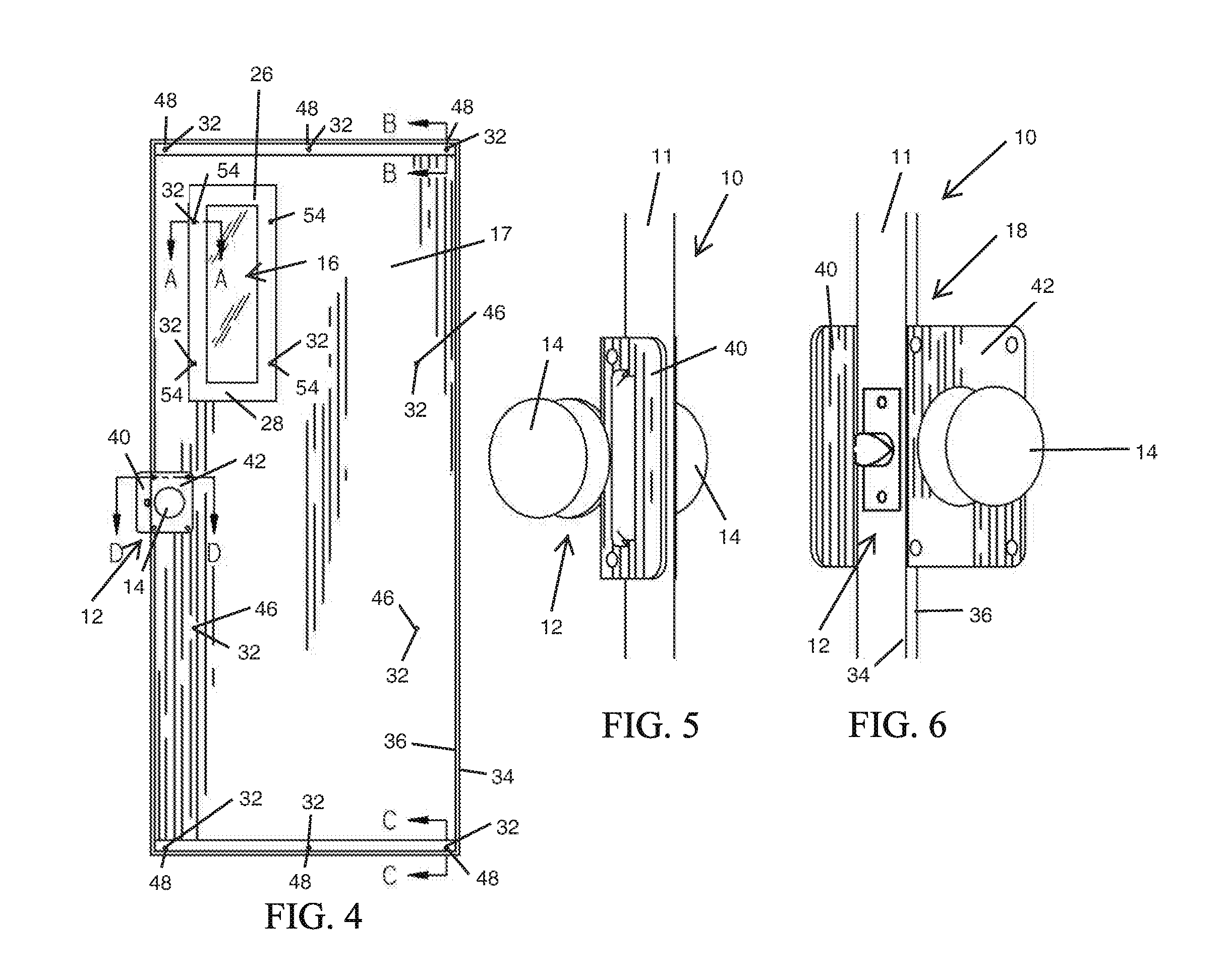
The present disclosure is about a new system and method for adding a layer of protection to existing school doors to prevent gunfire attacks. The system uses a thin, lightweight ballistic shield made of fiberglass reinforced plastic (FRP) material that is applied to the door as a retrofit and can withstand multiple gunfire blasts. The shield is custom fit to each door and held in place with clamps and fasteners. The technical effects of this system include providing a high level of protection without adding too much weight or cost to the door, as well as ensuring the shield remains secure during a fire alarm, and the door can still close properly without any modification.

Problems solved by technology

Because this material weighs approximately 6 pounds per square foot, providing that thickness would add too much weight to the door, would make it difficult for a single maintenance person to install, and would add unnecessary cost.
Moreover, by using lightweight (thinner) ballistic material, the added weight will not fatigue the existing door, nor will the shielding protection provided be exorbitantly expensive for schools.
Hence, to use adhesives to secure the ballistic skin to the door can add unnecessary complexity to a retrofit installation.
In short, the mechanical fasteners make for a fool-proof installation.
Ballistic fiberglass reinforced plastic (FRP) is difficult to bond to since it has a relatively “greasy” surface, so using mechanical fasteners and the top and bottom skin clamps solve any bonding issues.

Method used


Image

  • Classroom retrofit barriers
  • Classroom retrofit barriers
  • Classroom retrofit barriers

Examples


Embodiment Construction

[0030]Exemplary embodiments of the present disclosure will be best understood by reference to the drawings, wherein like parts are designated by like numerals throughout. It will be readily understood that the components of the exemplary embodiments of the present disclosure, as generally described and illustrated in the Figures herein, could be arranged and designed in a wide variety of different configurations. Thus, the following more detailed description of exemplary embodiments of the apparatus, system, and methods of the present disclosure, as represented in FIGS. 1 through 12, is not intended to limit the scope of the invention, as claimed, but is merely representative of exemplary embodiments.

[0031]The phrases “connected to,”“coupled to” and “in communication with” refer to any form of interaction between two or more entities, including mechanical, electrical, magnetic, electromagnetic, fluid, and thermal interaction. Two components may be coupled to each other even though t...


PUM


Abstract

A ballistic door providing barrier-of-entry shielding blocks a doorway in certain emergency situations to shield against active shooters, while not inhibiting, impeding, or changing the safe egress through the ballistic door. A ballistic assembly may be secured to the non-threat side of an existing door, by retrofit installation or by new construction installation. The ballistic assembly has a ballistic skin, a top ballistic skin clamp, and a bottom ballistic skin clamp. The top and bottom ballistic skin clamps secure the ballistic skin against the non-threat side of the door. The ballistic door has at least a N.I.J. Level IIIA of protection against gunfire.

Description

TECHNICAL FIELD[0001]This patent application claims the benefit of U.S. Provisional Patent Application Ser. No. 62 / 136,902 that was filed on Mar. 23, 2015, for an invention titled CLASSROOM RETROFIT BARRIER.TECHNICAL FIELD[0002]The present invention relates generally to ballistic barriers. More specifically, the present invention relates to a system and method for retrofitting an entryway to a classroom or the like.BACKGROUND[0003]In today's society there has arisen a need to provide protection for students against active shooters (gunmen) attacking defenseless victims on school campuses. There are many approaches being considered for such protection including but not limited to; more campus police, arming teachers, ballistic backpacks, etc.[0004]One approach is disclosed in U.S. Pat. No. 9,145,729 entitled Classroom Ballistic Barriers, issued Sep. 29, 2015 to DAW Technologies, LLC, where the barrier system comprised a ballistic panel nested slidably in upper and lower channels to s...

Claims


Application Information

Patent Timeline
Patent Type & Authority Applications(United States)
IPC IPC(8): E06B5/10E05C19/00E04H9/06F41H5/24
CPCE06B5/10E04H9/06E05C19/00F41H5/24E05B15/1614E05B65/0075E06B2003/7049F41H5/013F41H5/226F41H5/26
Inventor SPRANSY, PETER J.
Owner DAW TECH
Learn More