
Liquid natural gas transfer

a natural gas and liquid technology, applied in the direction of electrochemical generators, container discharging methods, container filling under pressure, etc., can solve the problems of long time-consuming and laborious, and long time-consuming for the transfer of large amounts of fuel in a shorter time. , to achieve the effect of reducing the number of times

Inactive Publication Date: 2016-09-29
KOSAN CRISPLANT AS
View PDF6 Cites 7 Cited by
  • Summary
  • Abstract
  • Description
  • Claims
  • Application Information

AI Technical Summary

Benefits of technology

The present invention provides an improved method and system for transferring liquid natural gas from one container to another. The invention addresses the short and long term efficiency of the system, as well as improves the environmental friendliness of the transfer operation when compared to existing methods and systems.

Problems solved by technology

Bunkering operation of a LNG fuelled marine vessel may take a long time.
The two-phase flow may cause control problems and pressure pulses, which may be harmful for the supply procedure and for the piping arrangements of the bunkering system.
A typical practice and trend in marine vessel operation of today is shortened port times and increased operating speeds, which leads to a transfer of larger amounts of fuel in a shorter time.

Method used


Image

  • Liquid natural gas transfer
  • Liquid natural gas transfer
  • Liquid natural gas transfer

Examples


Embodiment Construction

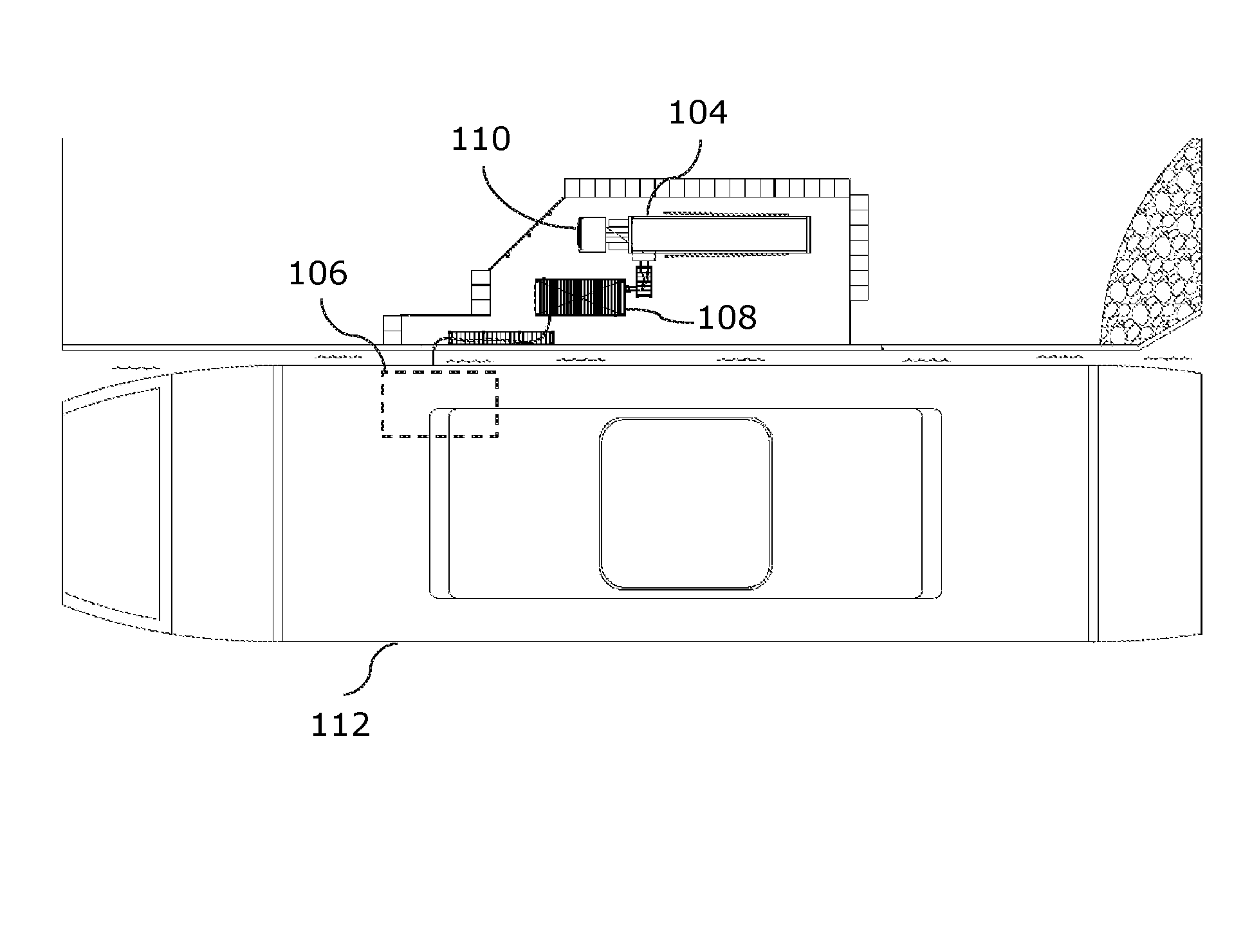
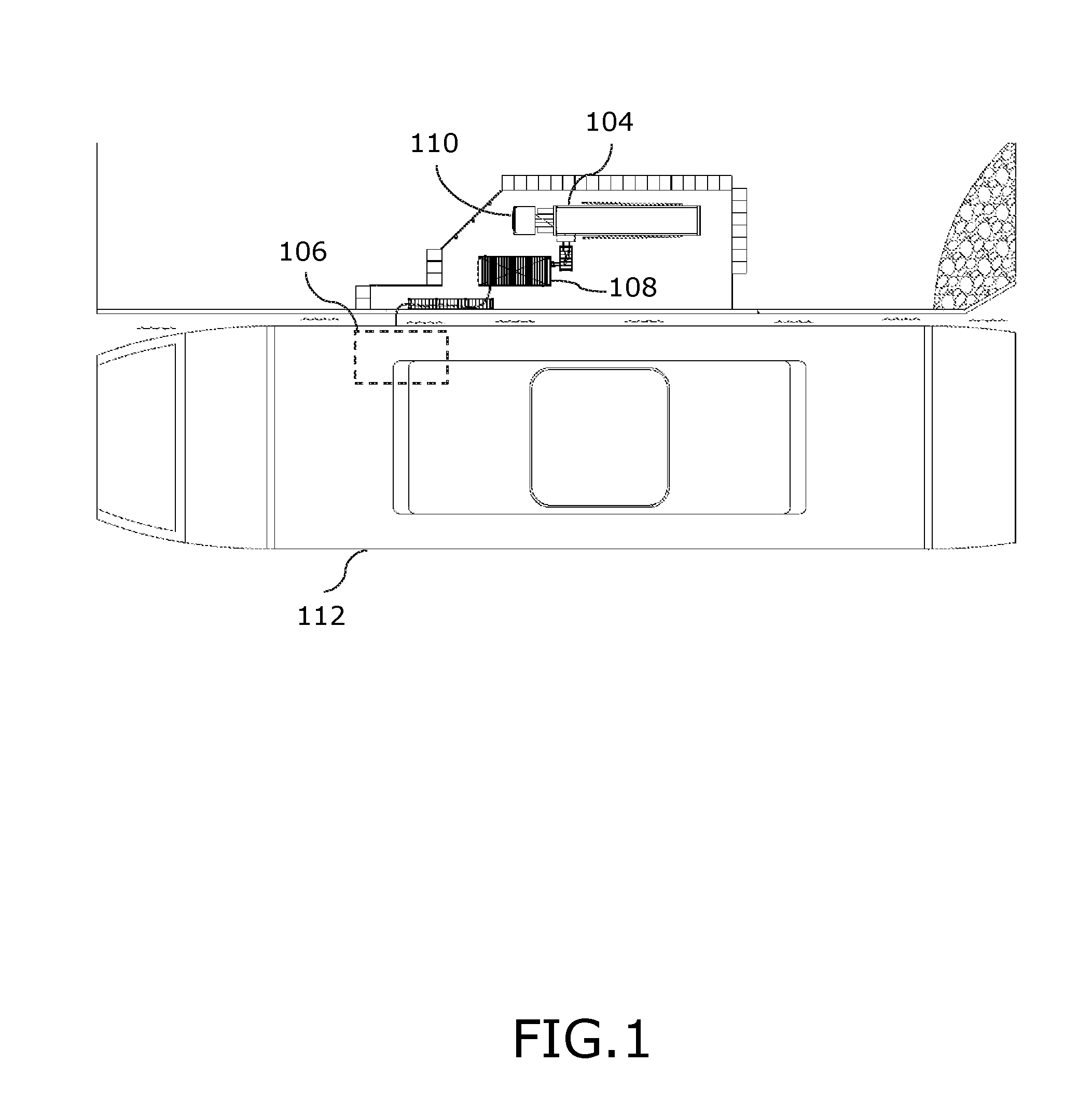
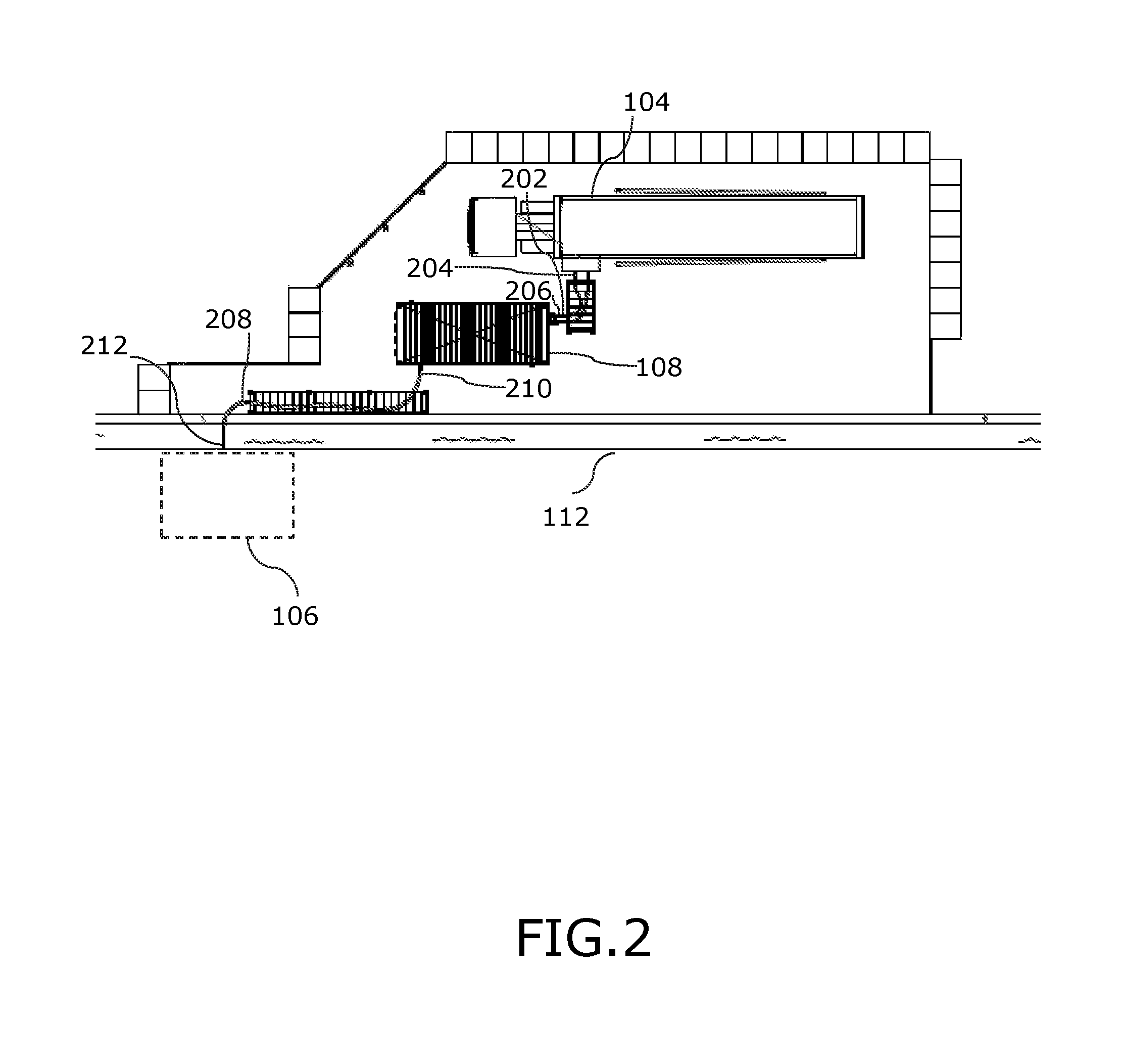
[0076]FIG. 1 is a top view of a site where LNG is transferred from a first container 104 to a second container 106 with a system for transfer of LNG. The first container is preferably a cryogenic LNG-ISO container. In the embodiment, the first container has arrived by truck and is positioned on a semitrailer, i.e. a trailer without a front axle, and is positioned in an enclosed area close to a pump station 108. In the shown embodiment the motored vehicle, embodied as a truck 110, which is positioned the first container next to the pump station is still on site. At least for some sites, the truck may leave the site and return again when the first container is empty and to replace the empty container with a filled one. In the shown embodiment, the second container 106 is included in a LNG powered ship 112, but could as well be a container in a truck or a container for a truck or for a ship.

[0077]The LNG-ISO container (first container) is preferably and as illustrated positioned within...


PUM


Abstract

In order to provide improved efficiency, e.g. in terms of how to operate and maintain a liquid natural gas (LNG) transfer system, while also improving the environmental friendliness of the transfer operation, there is disclosed a method and system of transferring liquid natural gas from a first container 104 to a second container 106 via a pump station 108. The first container 104 is positioned close to the pump station 108 by a truck 110, and the second container 106 is positioned close to the pump station 108 by a ship 112. Repeated transfer of LNG is provided using first and second dry couplings 304, 308 and, after transfer is complete, disconnecting the second dry coupling 308 from the second container and providing a flow of liquid natural gas back into the first container utilising an overpressure in the insulated pipes or hoses 202, 208 and in pipes of the pump station relatively to the pressure in the first container and by replacing the first container 104 with a filled first container when the first container is empty.

Description

FIELD OF THE INVENTION[0001]The invention relates to transfer of natural gas, which has been liquefied to become liquid natural gas (LNG) or liquefied natural gas (LNG), from a first to a second container. The invention is in an embodiment explained in connection with transfer of LNG to a second container positioned in a LNG powered vessel, ship or ferry, such as for a ferry route.BACKGROUND OF THE INVENTION[0002]Natural gas boils at a temperature of about minus 160° C.−minus 164° C. when under a pressure close to normal atmospheric pressure (about 101.3 kPa at sea level), mainly depending on the amount of methane in the gas, of which natural gas typically contains 80-95%.[0003]In order to provide an efficient, also in terms of cost, storage or transport of natural gas, the gas is liquefied into liquid state, LNG. LNG typically takes up about 0.15-0.2% of the volume of natural gas in gaseous state. LNG is typically transported in cryogenic, insulated containers by road or sea.[0004]...

Claims


Application Information

Patent Timeline
Patent Type & Authority Applications(United States)
IPC IPC(8): F17C5/02B63B25/12F17C7/02
CPCF17C5/02F17C7/02B63B25/12F17C2205/0355F17C2205/0364F17C2270/0105F17C2221/033F17C2227/0135F17C2265/065F17C2265/07F17C2205/037F17C2201/052F17C2201/054F17C2205/0332F17C2205/0367F17C2223/0161F17C2223/033F17C2225/0161F17C2225/033F17C2227/015F17C2227/044F17C2227/047F17C2270/0171F17C2270/0184
Inventor BJORN, ANDERSNIELSEN, ANDERS WURTZJORGENSEN, ANDERS DAHL
Owner KOSAN CRISPLANT AS
Learn More