Method for observing deformation of elastic material and apparatus for capturing projection image of elastic material

a technology of elastic material and projection image, which is applied in the direction of instruments, structural/machine measurement, and material analysis using wave/particle radiation

Inactive Publication Date: 2016-09-29
SUMITOMO RUBBER IND LTD
View PDF18 Cites 6 Cited by
  • Summary
  • Abstract
  • Description
  • Claims
  • Application Information

AI Technical Summary

Benefits of technology

[0038]The invention as set forth in claim 1 includes the projection image obtaining step of capturing the projection image of at least a part of the elastic material, from the direction perpendicular to the arbitrary axis of the elastic material, at the capture positions around the axis, the three-dimensional image constructing step of constructing the three-dimensional image of the elastic material from the projection images, and the step of observing the three-dimensional image.
[0039]The projection image obtaining step comprises the deforming step of deforming the elastic material in the predetermined cycles, the signal output step of outputting the capture signal at the predetermined specific time point during one cycle, and the capturing step for capturing the projection image of the elastic material based on the capture signal. The deforming step, the signal output step and the capturing step are performed at each of the capture positions.
[0040]Thus, according to the invention as set forth in claim 1, even when the elastic material is deformed periodically, always the projection images un...

Problems solved by technology

This method, however, does not teach to observe a deformed state at a tim...

Method used


Image

  • Method for observing deformation of elastic material and apparatus for capturing projection image of elastic material
  • Method for observing deformation of elastic material and apparatus for capturing projection image of elastic material
  • Method for observing deformation of elastic material and apparatus for capturing projection image of elastic material

Examples


working examples

Working Example A

[0184]According to the processing procedures shown in FIGS. 6, 7 and 8, with respect to an elastic material making linear reciprocating motions, a specific deformed state (a state in which the compressive deformation of the elastic material was maximum) of the elastic material was observed (working example 1).

Furthermore, according to the processing procedures same as those of working example 1, a specific deformed state of the elastic material containing marker particles was observed (working example 2).

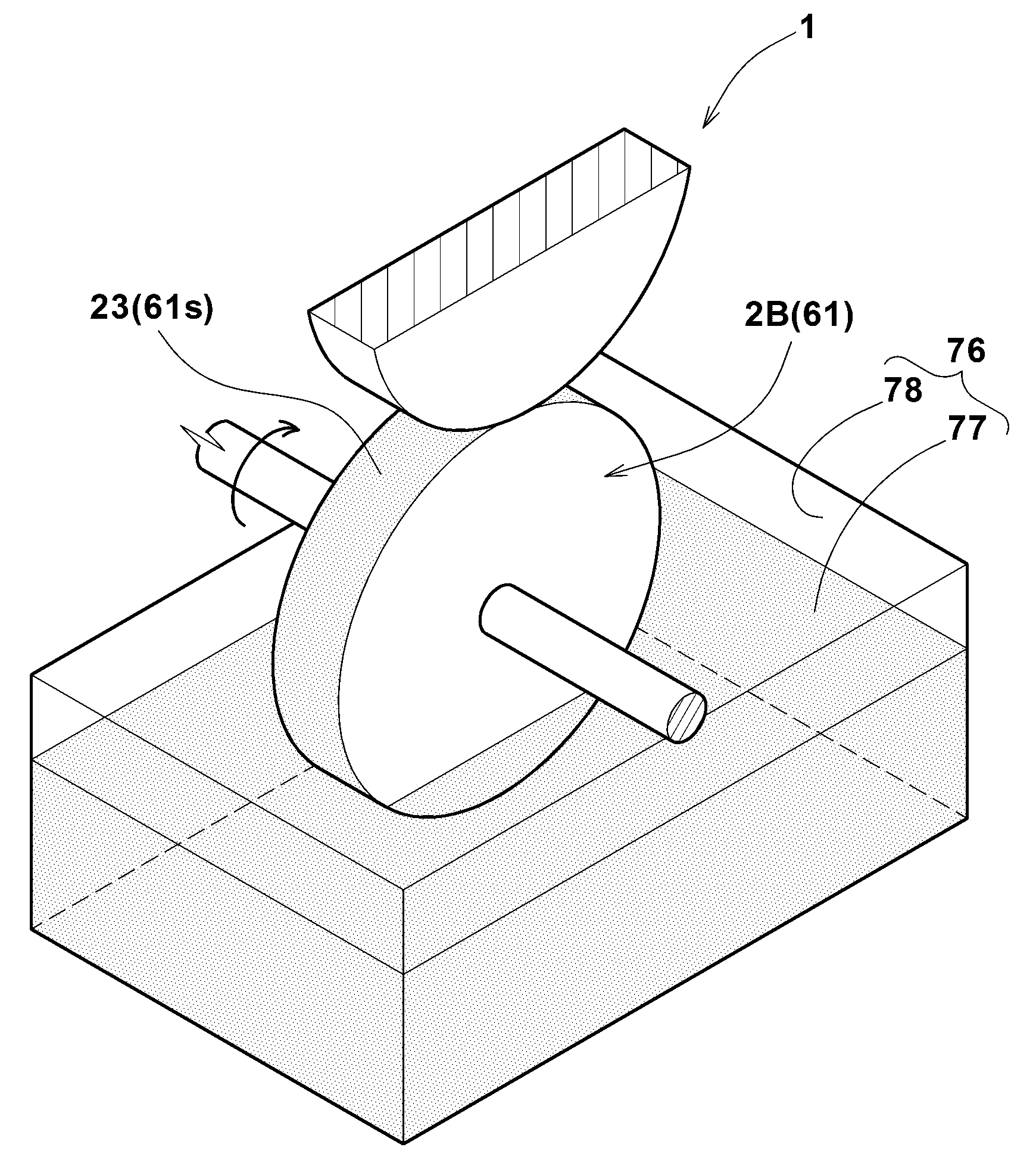
[0185]In accordance with the processing procedures shown in FIGS. 6, 7 and 14, with respect to the elastic material being rotating, a specific deformed state of the elastic material (at a time point when a specific position of the outer peripheral surface of the elastic material came into contact with a specific position of the outer peripheral surface of the drum) was observed (working example 3).

In the working example 3, the fluid supply means was used.

Common spec...

working example b

[0207]According to the processing procedures shown in FIGS. 6, 7 and 18, with respect to the elastic material rolling with the given slip angle, a specific deformed state of the elastic material (a state in which the compressive deformation of the elastic material was maximum) was observed (working example 4). Specifications of the elastic material was the same as Working Example 3 above.

Test conditions were as follows.

The size of the drum:

[0208]outer diameter D3: 120 mm

[0209]width: 20 mm

load of elastic material: 20 N

slip angle of elastic material: 1 degree

[0210]FIG. 21 is a cross-section of the three-dimensional image constructed according to Working Example 4.

FIG. 22 is another cross-section of the three-dimensional image constructed according to Working Example 4.

[0211]As apparent from FIGS. 21 and 22, in the observing method of Working Example 4, a clear three-dimensional image of the elastic material in a state approximate to the tire during running with the given slip angle wa...


PUM


Abstract

To observe an elastic material under a dynamically deformed state. [Solution] A method for observing deformation of an elastic material 1 including rubber or elastomer, and an apparatus for capturing a projection image of the elastic material suitably used therefor. The observing method includes: a projection image obtaining step S1 of capturing a projection image of at least a part of the elastic material 1, from a direction perpendicular to an arbitrary axis of the elastic material 1, at a plurality of capture positions P around the axis; a three-dimensional image constructing step S2 of constructing a three-dimensional image 51 of the elastic material 1 from the projection images, and a step of observing the three-dimensional image 51. The projection image obtaining step S1 comprises: a deforming step S12 of deforming the elastic material 1 in predetermined cycles; a signal output step S13 of outputting an capture signal St at a predetermined specific time point during one cycle; and a capturing step S14 of capturing the projection image of the elastic material 1 based on the capture signal St. The deforming step S12, the signal output step S13 and the capturing step S14 are performed at each of the capture positions.

Description

TECHNICAL FIELD[0001]The present invention relates to a method for observing an elastic material under dynamically deformed state, and an apparatus for capturing a projection image of the elastic material suitably used for that purpose.BACKGROUND ART[0002]In the following Patent Document 1, there has been disclosed an observing method for obtaining an image relating to an interior of a friction material by transmitting radiation light through the interior of the friction material.This method, however, does not teach to observe a deformed state at a time point when the deformation of the friction material is periodical for example.Patent Document 1: Japanese Unexamined Patent Publication No. 2009-85732DISCLOSURE OF THE INVENTIONProblems to be Solved by the Invention[0003]The present invention was made in view of the circumstances as described above, and a main object is to provide an observing method capable of observing a particular deformed state (deformation moment) of a periodica...

Claims


Application Information

Patent Timeline
IPC IPC(8): G01N23/04G01M17/03G01B15/06
CPCG01N23/046G01B15/06G01N2223/419G01N2223/627G01N2223/401G01M17/028G01M17/027G01N23/04
Inventor MASHITA, RYOKISHIMOTO, HIROYUKI
Owner SUMITOMO RUBBER IND LTD
Why Eureka
Try Eureka