System for Locating an Object using an Antenna Array with Partially Overlapping Coils

a technology of antenna array and object, applied in the field of sensing and detecting systems, can solve the problems of time required to complete, differing procedures, and inability to ensure the correct placement of catheters, and achieve the effect of accurate detection of electromagnetic reflectors

Active Publication Date: 2016-09-29
TECH UNIV EINDHOVEN
View PDF1 Cites 3 Cited by
  • Summary
  • Abstract
  • Description
  • Claims
  • Application Information

AI Technical Summary

Benefits of technology

The invention has several benefits: it works well no matter what kind of people are wearing or where they're located; its detector can be easily spotted even in environments that produce strong signals; it requires minimal amounts of energy to operate and can accurately detect tiny objects within the body.

Problems solved by technology

The technical problem addressed in this patent text is the need for technology to aid clinical personnel in determining the position of tubes and catheters inserted in critically ill and fragile patients, to avoid misinterpretations and misplacement which could result in death of the patient. Existing medical procedures are posed on reliability, safety, costs and usability, and there is a need for technology that can improve the accuracy and precision of these procedures.

Method used


Image

  • System for Locating an Object using an Antenna Array with Partially Overlapping Coils
  • System for Locating an Object using an Antenna Array with Partially Overlapping Coils
  • System for Locating an Object using an Antenna Array with Partially Overlapping Coils

Examples


Embodiment Construction

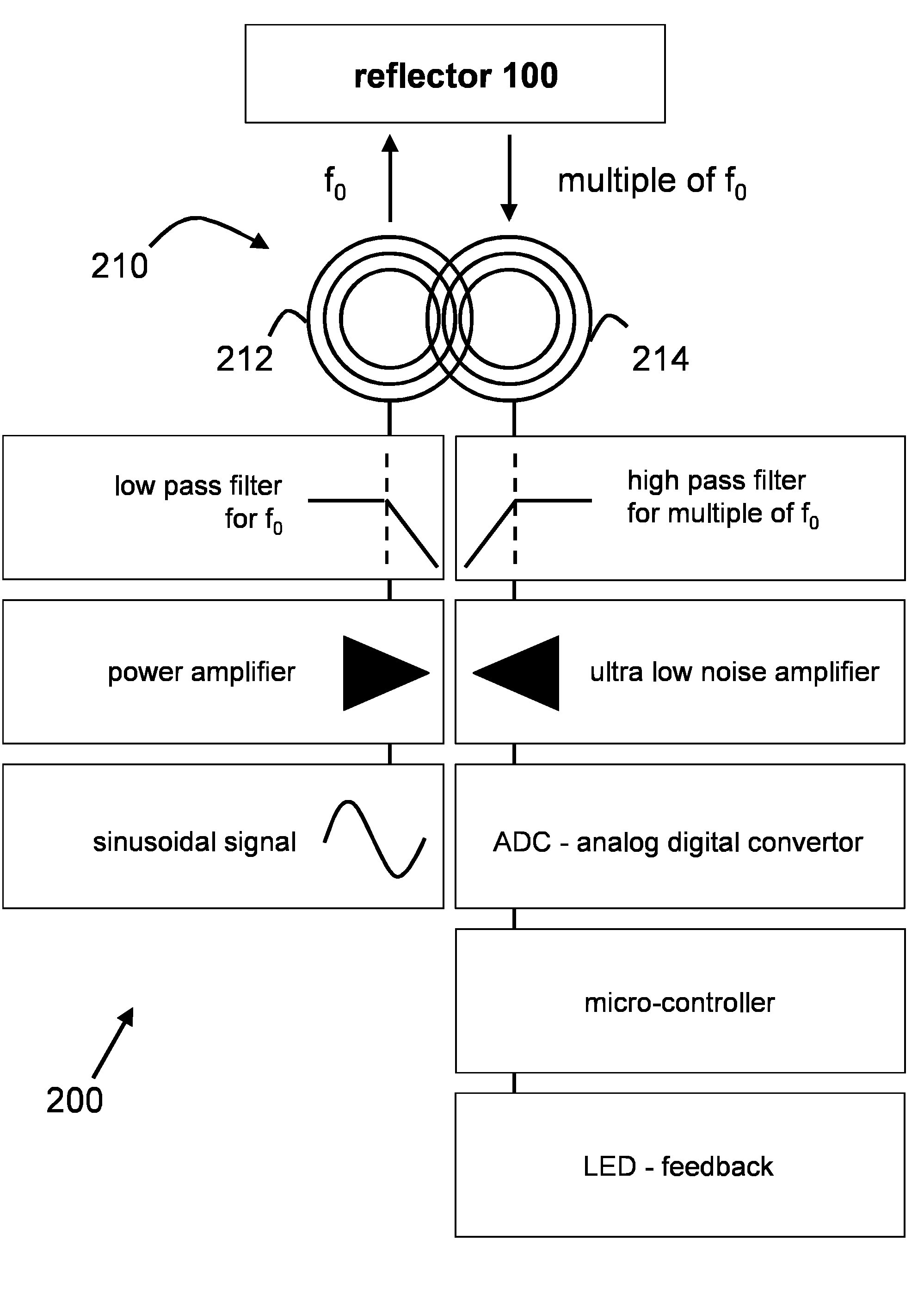
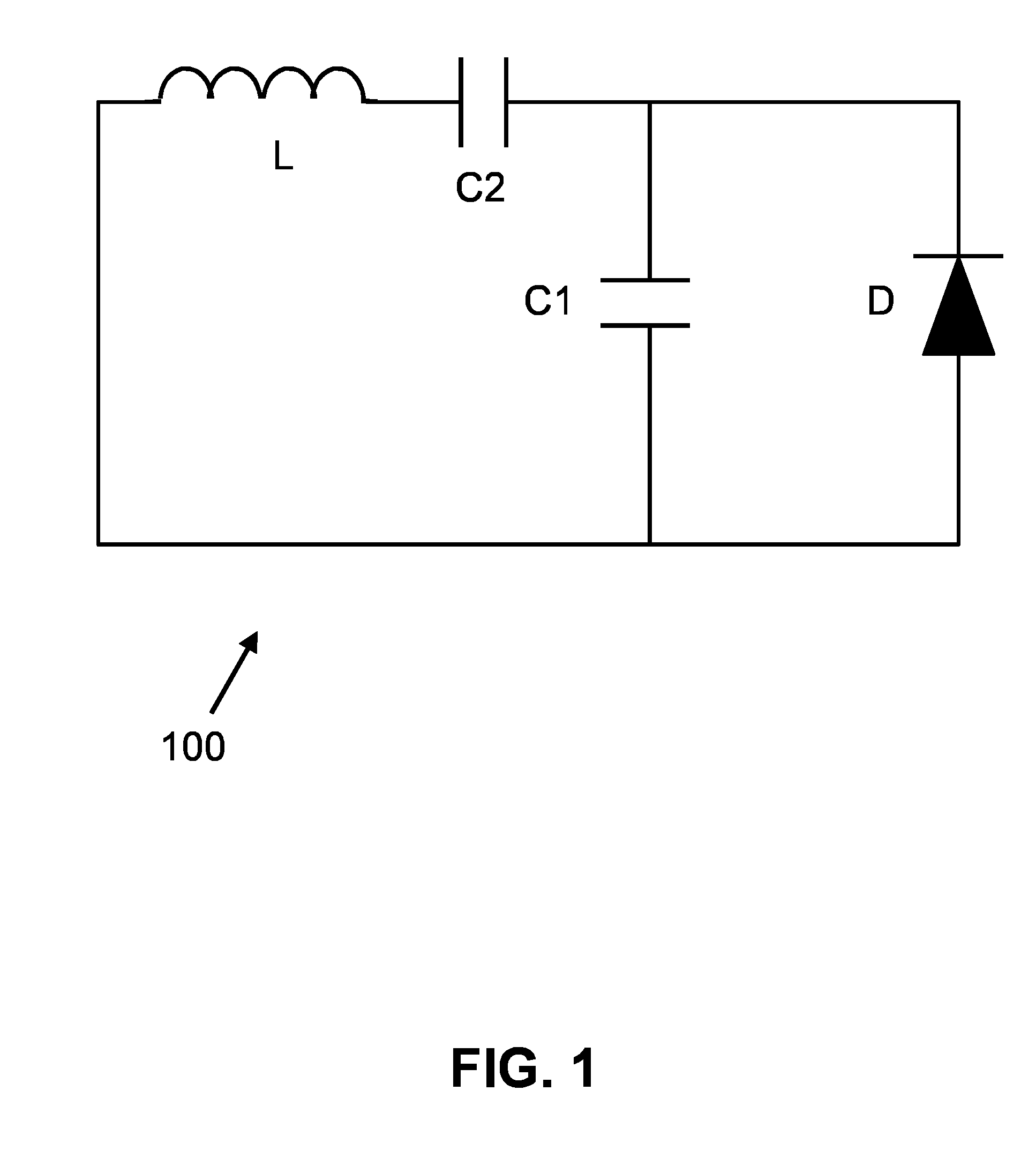
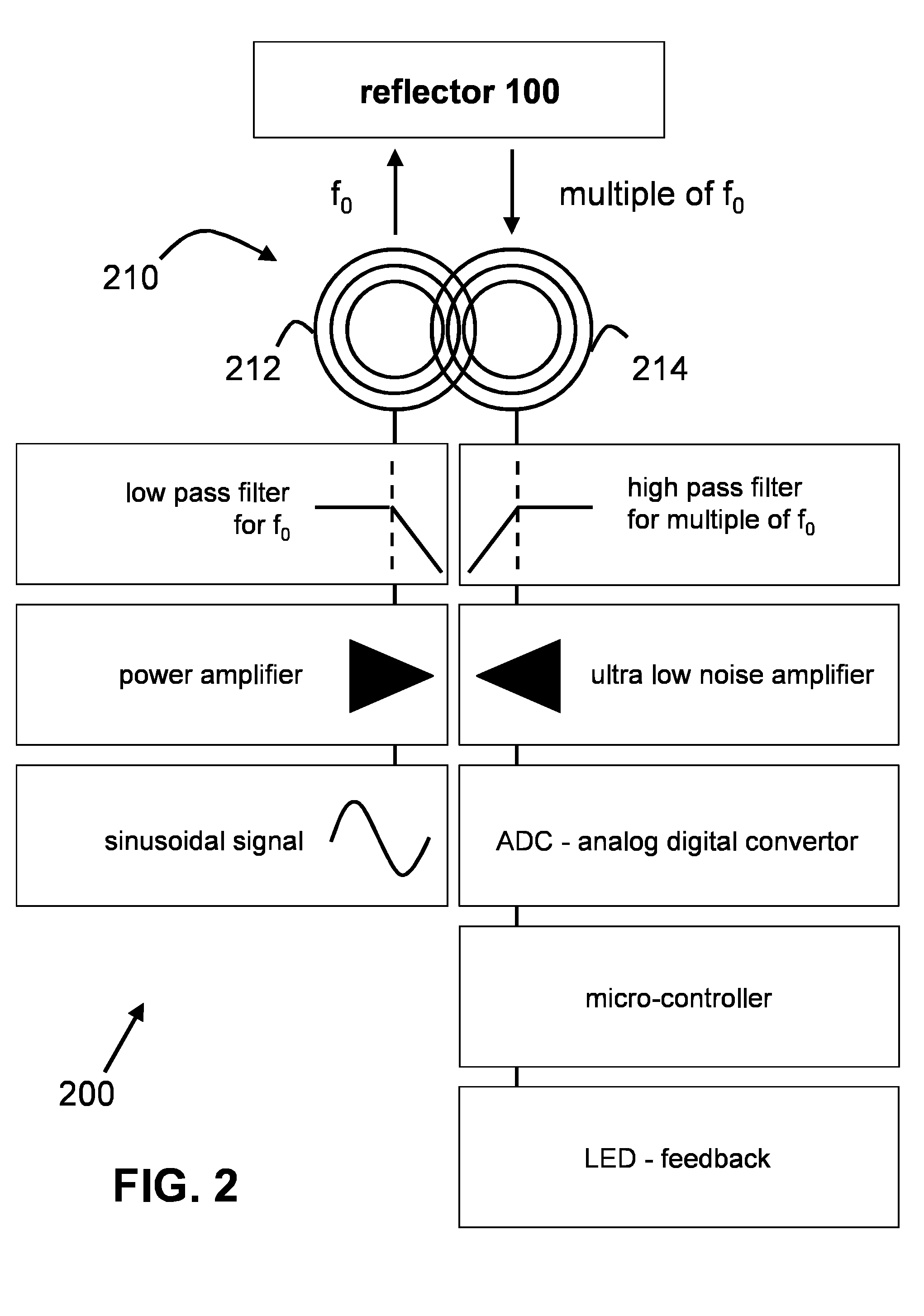
[0011]The invention is a system for wirelessly locating an object, especially objects that are hidden from direct visual inspection. In a specific embodiment the object to be located is a tip of a nasogastric feeding tube that is inserted in a human body. However, the invention is not limited to various medical applications and can also be useful in any other situation where a hidden object needs to be located or tracked. The system contains a transducer or electromagnetic (EM) reflector 100 and a scanner or transceiver unit 200 as shown in respectively FIGS. 1-2. In one variation the scanner can be equipped with sensors, such as an accelerometer to keep track of the direction of movement.

Reflector

[0012]Transducer or electromagnetic (EM) reflector 100 is a passive (i.e. wirelessly powered) electromagnetic reflector that can be affixed to an object that one desires to locate. The electromagnetic reflector contains a ferrite antenna (coil) L with a diode D and a series C2 and parallel...


PUM


Abstract

A system is provided for wirelessly locating objects. The system has a transceiver unit with an antenna array of two partially overlapping coils, which is used in combination with a passive electromagnetic reflector to track or locate the objects. The system is tuned to reflect and receive higher order harmonics of a transmitted signal frequency. The system is reliable in a highly reflective environment with no placement error detection due to reflections. A relatively large distance can be bridged with a minimum power and a small sensitive area to detect the coils, which increase the accuracy to determine the location of the electromagnetic reflector.

Description


Claims


Application Information

Patent Timeline
Owner TECH UNIV EINDHOVEN
Why Eureka
Try Eureka