Virtual image display apparatus

a virtual image and display device technology, applied in the field of virtual image display devices, can solve the problems of high brightness, long life, and difficulty in using image lights

Active Publication Date: 2016-09-29
SEIKO EPSON CORP
View PDF3 Cites 13 Cited by
  • Summary
  • Abstract
  • Description
  • Claims
  • Application Information

AI Technical Summary

Benefits of technology

[0027]In the virtual image display apparatus, the reflection film having wavelength dependence with different reflectance depending on the wavelength range is formed on the mirror reflection surface at the light-incident side of the light guide member, and thereby, control may be made so that the uniform color balance of the image lights through the reflection film may be achieved and images in good conditions ma

Problems solved by technology

However, in the case of using the OLED or the like, there are problems in higher brightness and longer life.
It i

Method used


Image

  • Virtual image display apparatus
  • Virtual image display apparatus
  • Virtual image display apparatus

Examples


first embodiment

[0041]As below, a virtual image display apparatus according to the first embodiment of the invention will be explained in detail with reference to FIG. 1 etc.

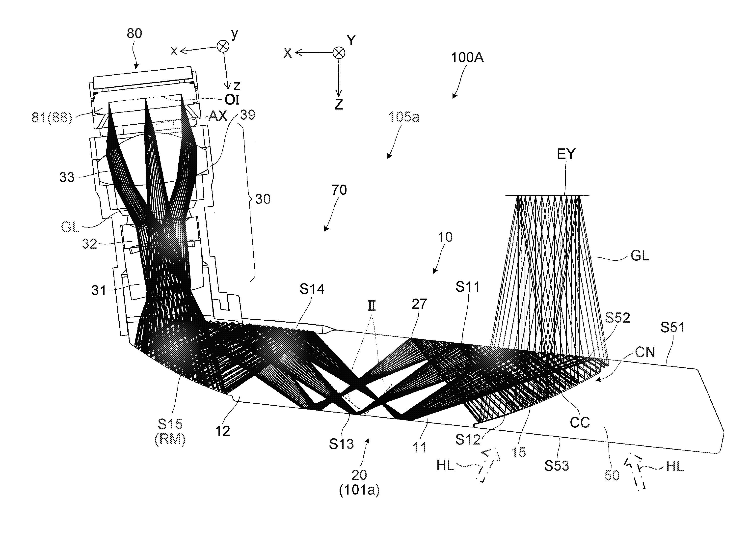
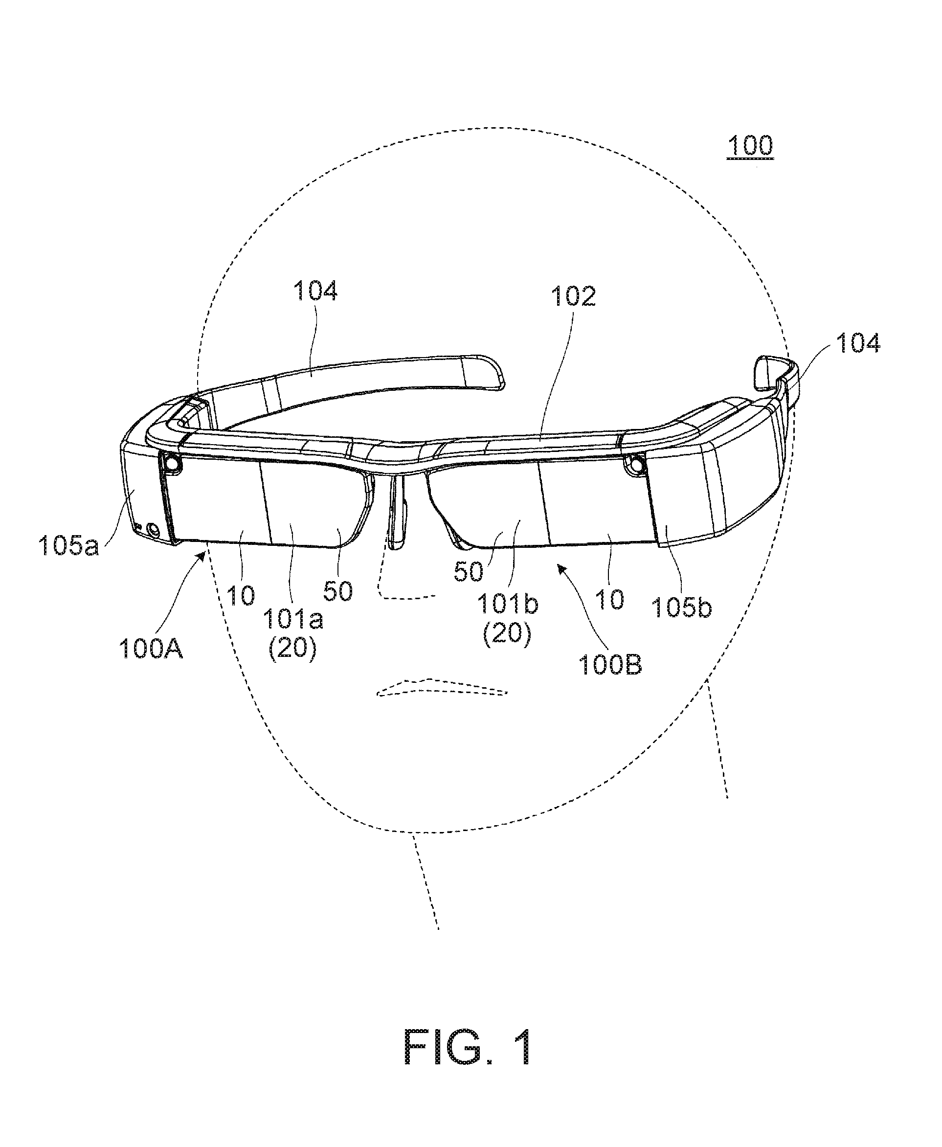
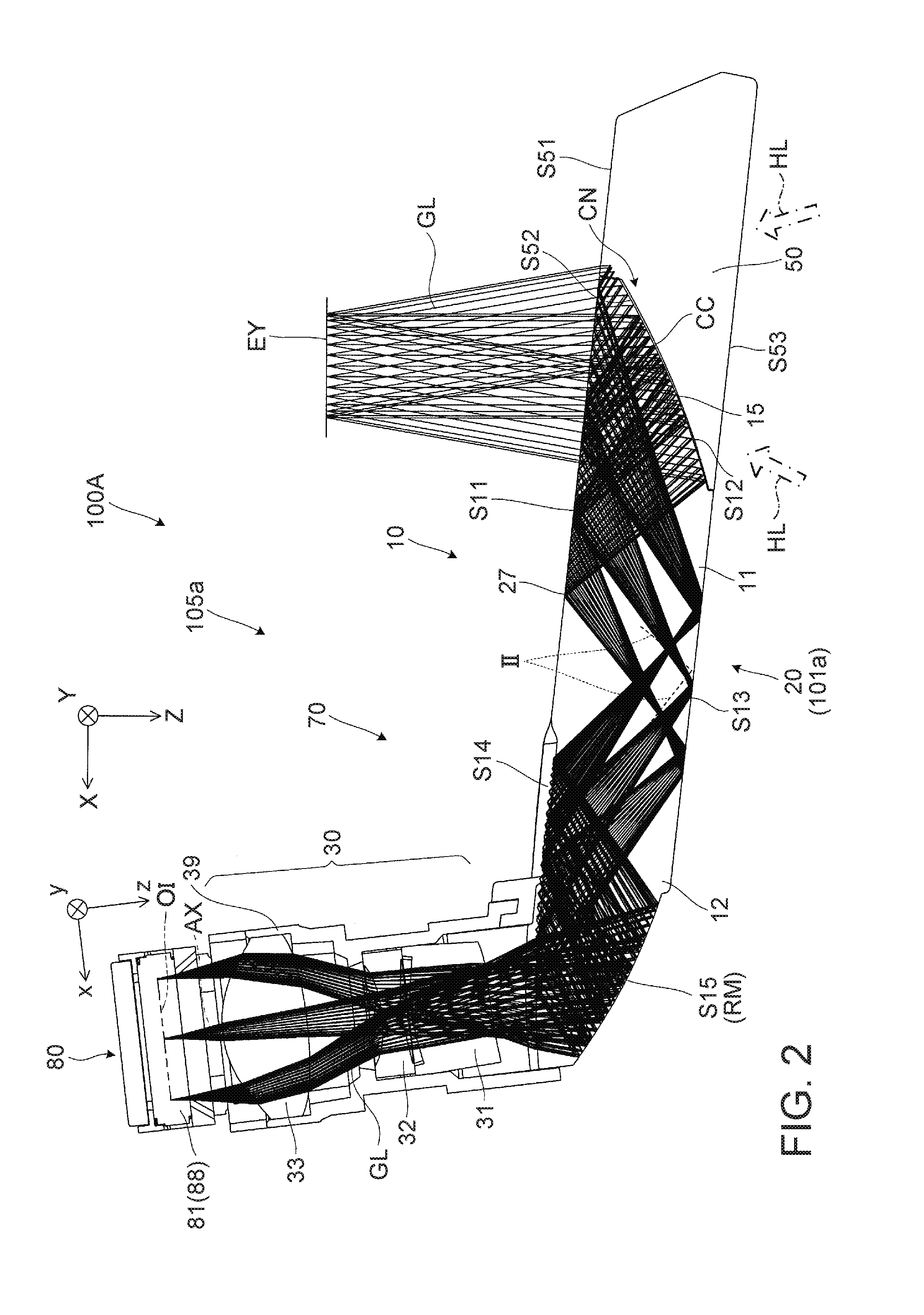
[0042]As shown in FIGS. 1 and 2, a virtual image display apparatus 100 of the embodiment is a head mounted display having an appearance like spectacles, and a virtual image display apparatus that enables an observer or a user wearing the virtual image display apparatus 100 to visually recognize image lights (picture lights) by virtual images and visually recognize or observe an outside world image in see-through vision. The virtual image display apparatus 100 includes first and second optical members 101a, 101b for see-through covering in front of eyes of the observer, a frame part 102 that supports both of the optical members 101a, 101b, and first and second image formation main body parts 105a, 105b added to parts from both of the left and right ends of the frame part 102 to posterior temple parts (temples) 104. Here, a first...

second embodiment

[0062]Hereinafter, a virtual image display apparatus according to the second embodiment will be explained. Note that the embodiment is a modified example of the virtual image display apparatus of the first embodiment and the same as the first embodiment except the structure of the reflection film having wavelength dependence, and the overall illustration and explanation will be omitted.

[0063]FIG. 5 is a graph showing a relationship between reflection characteristics of the reflection film having wavelength dependence, i.e., the half-mirror layer 15 (see FIG. 2) and a spectrum of light source light in the picture device having the light emitting part in the virtual image display apparatus according to the embodiment. Note that, in the graph, a curve C1 shows the reflection characteristics of the half-mirror layer 15 and a curve C2 shows the spectrum of the light source light in the picture device. Note that, in the virtual image display apparatus according to the embodiment, the conf...

third embodiment

[0065]As below, a virtual image display apparatus according to the third embodiment will be explained. The virtual image display apparatus according to the embodiment is different from the cases of the respective embodiments in that a see-through compensation part is further provided in the respective configurations exemplified as the respective embodiments. Note that the embodiment is a modified example of the virtual image display apparatus of the first embodiment and the structure except the see-through compensation part is the same as that of the first embodiment, and the overall illustration and explanation will be omitted.

[0066]FIG. 6 is a diagram for explanation of one configuration example of a see-through compensation part PC in the virtual image display apparatus according to the embodiment and a partially enlarged view conceptually showing the half-mirror layer 15 as the reflection film having wavelength dependence and a state around. As illustrated, the see-through compe...


PUM


Abstract

In an image generation unit, a light emitting part is formed using a self-emitting OLED device, and thereby, high-contrast images can be formed and the life of the light emitting part and the life of the virtual image display apparatus are extended. Even when the light emitted in the light emitting part has deviation in color balance, a half-mirror layer that has light transmissivity and realizes see-through vision is a reflection film having wavelength dependence, and thereby, a uniform color balance of image lights is achieved and images in good conditions are visually recognized.

Description

BACKGROUND[0001]1. Technical Field[0002]The present invention relates to a virtual image display apparatus including a head mounted display that presents images formed by an image display device or the like to an observer.[0003]2. Related Art[0004]Various systems have been proposed as optical systems incorporated in virtual image display apparatuses including head mounted displays (hereinafter, also referred to as HMDs) attached to heads of observers. Of them, for example, for preventing generation of ghost light due to image lights, systems with characteristics in layer or film parts for adjustment and control of lights such as a system having a bonding layer for bonding a part in which a half mirror of optical components is formed contains a dye (see Patent Document 1 (JP-A-2012-168425)) and a system having a half mirror that reduces variations in reflectance with respect to incident angles of lights (see Patent Document 2 (JP-A-2010-230771)) are known.[0005]Here, in an HMD or the...

Claims


Application Information

Patent Timeline
IPC IPC(8): G02B27/01F21V8/00G02B5/26G02B27/14
CPCG02B27/0172G02B27/141G02B2027/0118G02B5/26G02B2027/0116G02B6/0055
Inventor MIYAO, TOSHIAKITOTANI, TAKAHIROTAKAGI, MASAYUKITAKEDA, TAKASHIKOMATSU, AKIRAKOSHIHARA, TAKESHIYANO, KUNIHIKO
Owner SEIKO EPSON CORP
Why Eureka
Try Eureka