
Wireless Power Alignment Guide

a technology of alignment guide and wireless power transfer, which is applied in the direction of transformers, basic electric elements, inductances, etc., can solve the problems of increasing the likelihood of meeting emi compliance requirements, and achieve the effect of less magnetic field, increased likelihood of meeting emi compliance requirements, and greater amounts of power

Active Publication Date: 2016-09-29
CHARGEDGE INC
View PDF2 Cites 10 Cited by
  • Summary
  • Abstract
  • Description
  • Claims
  • Application Information

AI Technical Summary

Benefits of technology

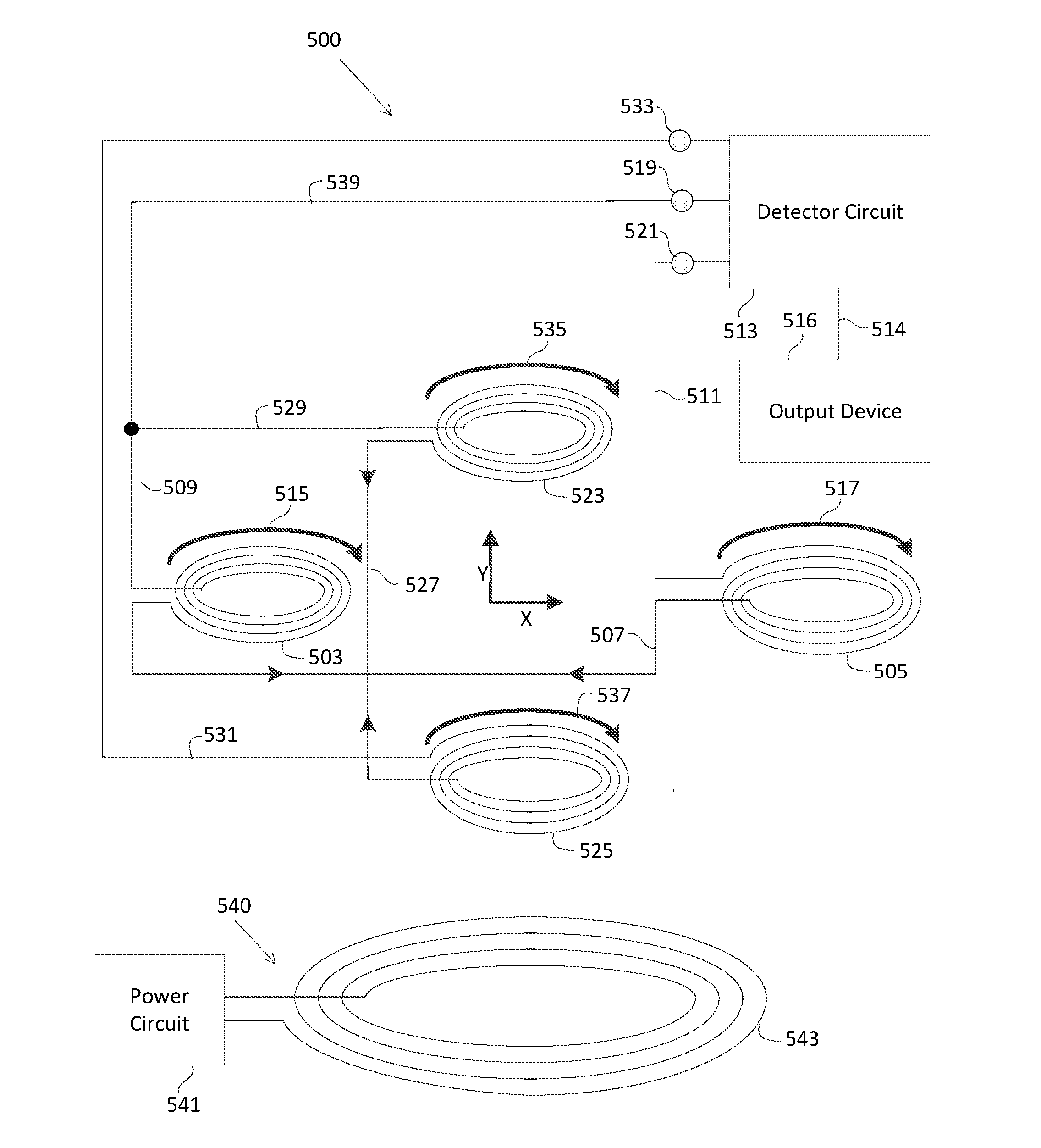
The patent describes a wireless power alignment guide that uses multiple coils and a detector circuit to calculate the offset between a wireless power receiver and a wireless power transmitter. This offset is important for aligning the receiver and the transmitter for optimal power transfer. The guide can be visually, audibly, and / or tactilely feedback to the user, and it helps to meet EMI compliance requirements. The guide can be implemented in a receiver device that includes a receiver coil and can generate a DC voltage, filter noise, and regulate the generated DC voltage under load. The guide is also effective when oriented perpendicular to the magnetic field generated by the wireless power transmitter. Overall, the guide simplifies the process of aligning wireless power receivers and transmitters for efficient power transfer.

Problems solved by technology

Further, aligning the transmitter and receiver results in less of the magnetic field generated by the transmitter radiating into the atmosphere, increasing the likelihood of meeting EMI compliance requirements.

Method used


Image

  • Wireless Power Alignment Guide
  • Wireless Power Alignment Guide
  • Wireless Power Alignment Guide

Examples


Embodiment Construction

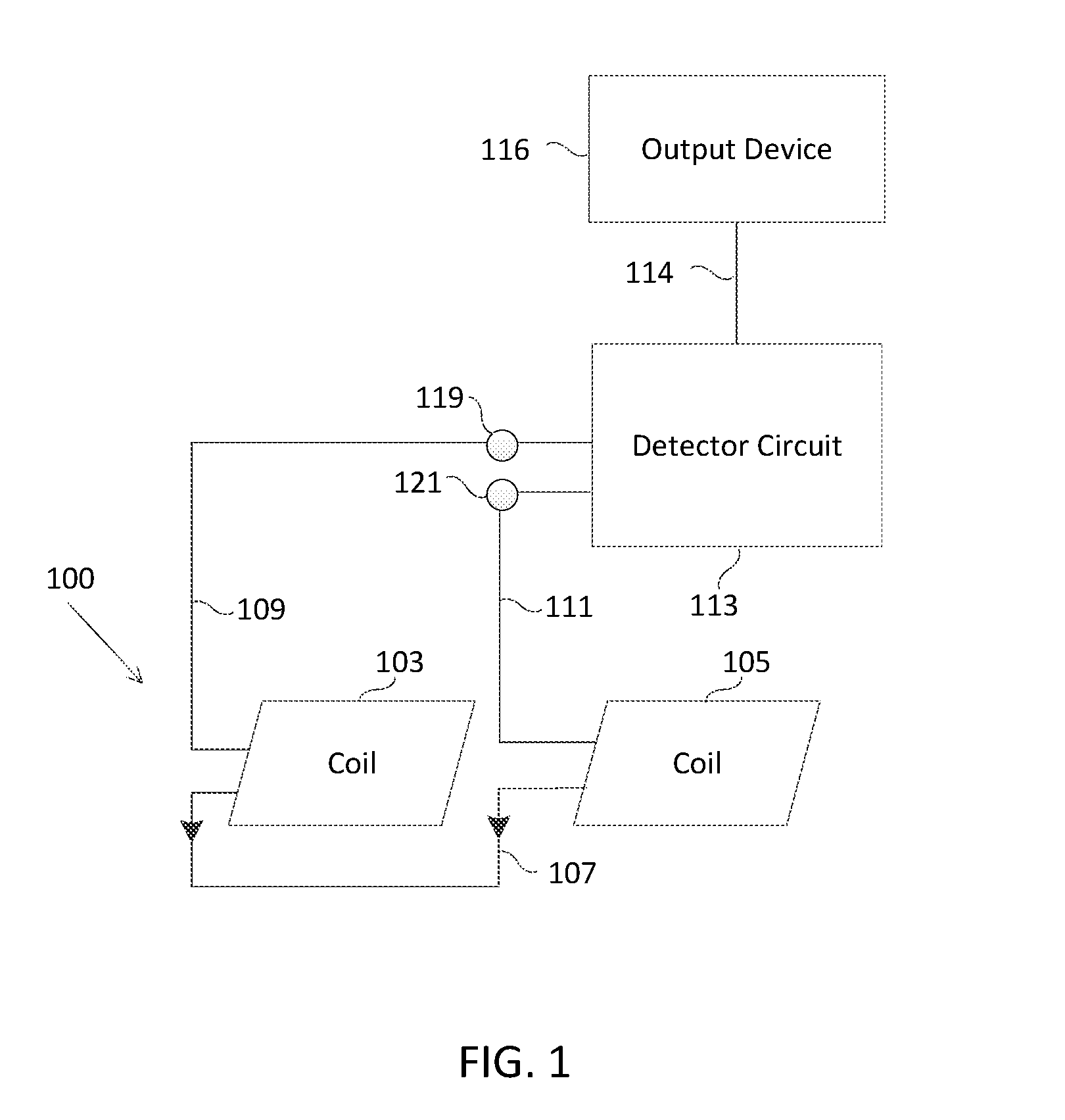
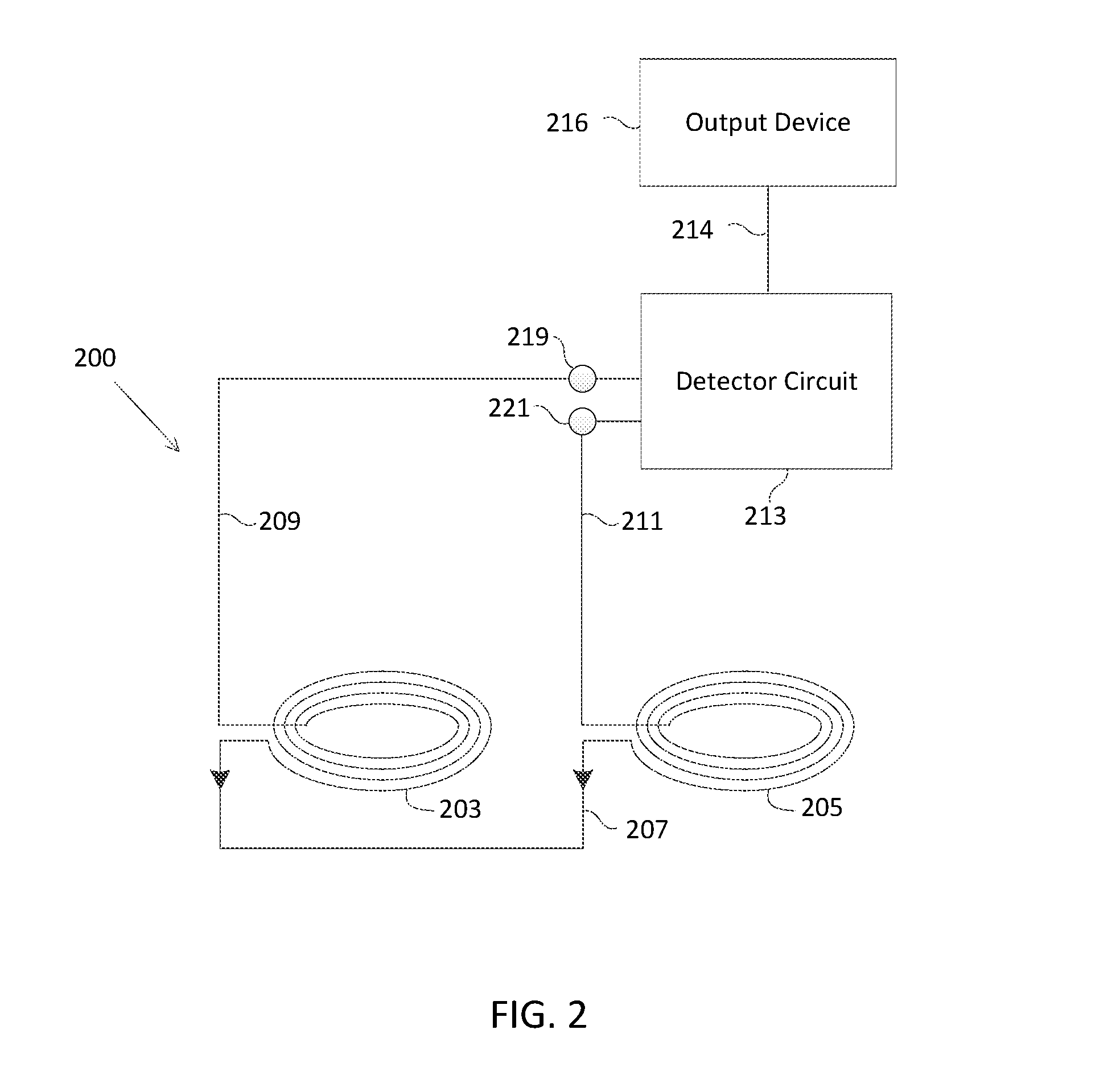
[0021]FIG. 1 is a block diagram of one embodiment of a wireless power alignment guide 100 using two coils. A coil 103 and a coil 105 are preferably identical coils with substantially the same shape, equal number of turns and substantially the same area. Coil 103 and coil 105 can be any shape, including, for example, circular, square or triangular. Coil 103 and coil 105 are configured in series and are oriented in a single plane. For example, coil 103 and coil 105 of wireless power alignment guide 100 can be incorporated within a smartphone device that can be charged wirelessly, and oriented on a plane that is geometrically parallel with the surface of the smartphone device that is intended to receive power wirelessly. If a user places the smartphone device over a wireless power transmitter that generates a magnetic field (not shown), coil 103 and coil 105 would be oriented perpendicular to the magnetic field generated by the wireless power transmitter. This configuration maximizes t...


PUM

PropertyMeasurementUnit
frequencyaaaaaaaaaa
frequenciesaaaaaaaaaa

Abstract

In one embodiment, a wireless power alignment guide uses multiple coils and a detector circuit to determine an offset between a wireless power receiver and a wireless power transmitter. A transmitter generates a magnetic field that causes a first time-varying current to flow in a first coil and a second time-varying current to flow in a second coil of the wireless power alignment guide. The first time-varying current can flow to the second coil and the second time-varying current can flow to the first coil. A detector circuit detects a voltage resulting from the first time-varying current and the second time-varying current and determines an offset so the user can center the receiver with the transmitter. By correcting any offset between the receiver and the transmitter, greater amounts of power can be transferred to the receiver in comparison to a receiver that is offset from a transmitter.

Description

CROSS-REFERENCE TO RELATED APPLICATION[0001]This application claims the benefit of U.S. Provisional Patent Application No. 62 / 142,465, entitled “Wireless Power Alignment Guide, and ” filed on Apr. 2, 2015 and U.S. Provisional Patent Application No. 62 / 139,785, entitled “Wireless Power Transfer Method Using Multiple Coil Arrays,” filed on Mar. 29, 2015. The subject matter of the related applications is hereby incorporated by reference in its entirety.FIELD OF THE INVENTION[0002]This invention relates generally to wireless power transfer and more specifically to an alignment guide for wireless power transfer.BACKGROUND[0003]Electronic devices typically require a connected (wired) power source to operate, for example, battery power or a wired connection to a direct current (“DC”) or alternating current (“AC”) power source. Similarly, rechargeable battery-powered electronic devices are charged using a wired power-supply that connects the electronic device to a DC or AC power source. The...

Claims


Application Information

Patent Timeline
Patent Type & Authority Applications(United States)
IPC IPC(8): H02J50/10H02J50/40H01F27/28
CPCH02J50/10H02J50/40H01F27/2804H01F27/402H01F38/14H02J50/005H02J50/90
Inventor MANIKTALA, SANJAYA
Owner CHARGEDGE INC
Learn More