helmet

a technology for helmets and helmet covers, applied in helmets, helmet covers, headwear, etc., can solve the problems of torsional force caused by impact being very serious, and achieve the effects of reducing impact friction, and reducing rotational or spin forces

Active Publication Date: 2016-10-06
PROTECTIVE SPORTS EQUIP INT
View PDF35 Cites 3 Cited by
  • Summary
  • Abstract
  • Description
  • Claims
  • Application Information

AI Technical Summary

Benefits of technology

[0008]The invention is directed to a helmet cover, and helmet comprising a helmet cover, that has an outer skin, an impact absorbing material and at least one vent comprising an aperture through the helmet cover. The impact absorbing material may be configured over substantially the entire helmet cover surface, or may cover only a portion of the helmet surface. In one embodiment, the impact absorbing material is configured as a discrete pad, in locations where impact is most common, such as on the front, sides, or back of the helmet. The impact absorbing material may be configured under the outer skin, or partially under the outer skin. There may be areas were the outer skin is absent and the impact absorbing material may be exposed to, or serve as, the outer surface of the helmet cover. In other embodiments, the impact absorbing material may be a discrete pad that may be interchanged or replaced as required. A vent may couple with an inner surface flow enhancer feature configured to distribute a flow of air from a vent over the inner surface and between the helmet cover and the helmet. An inner surface of the helmet cover may comprise a decoupling feature configured to allow the helmet cover to slide or slip slightly during an impact, thereby reducing rotational or spin forces. In addition, the outer surface of a helmet cover may be configured with deflection feature, such as a plurality of protrusion or dimples that are configured to reduce the outer most contact surface area and reduce impact through deflection. The reduced outer most contact surface area is configured to reduce friction of an impact.

Problems solved by technology

Twisting or torsional force caused by an impact can be very serious, as they sometimes lead to neck fractures, for example.

Method used


Image

  • helmet
  • helmet
  • helmet

Examples


Embodiment Construction

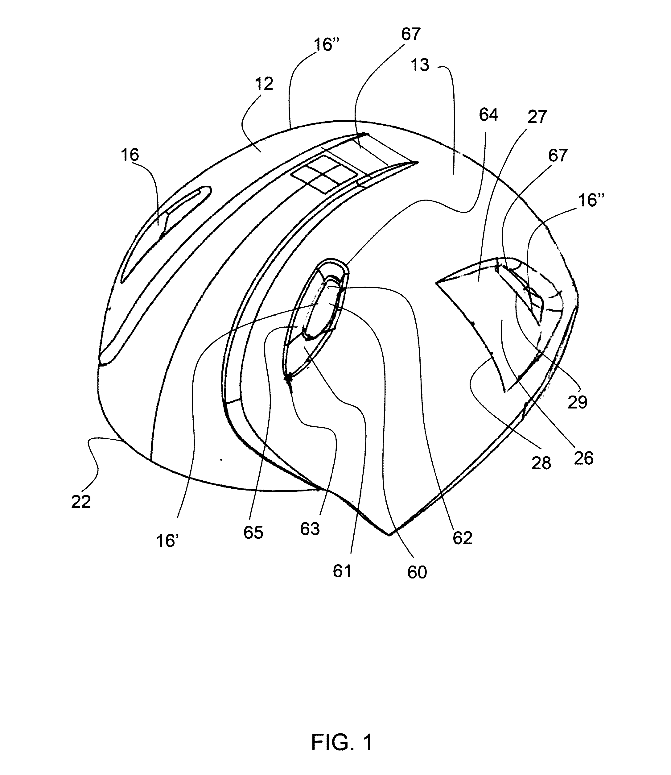
[0030]FIG. 1 shows an isometric view of an exemplary helmet over having a plurality of vents.

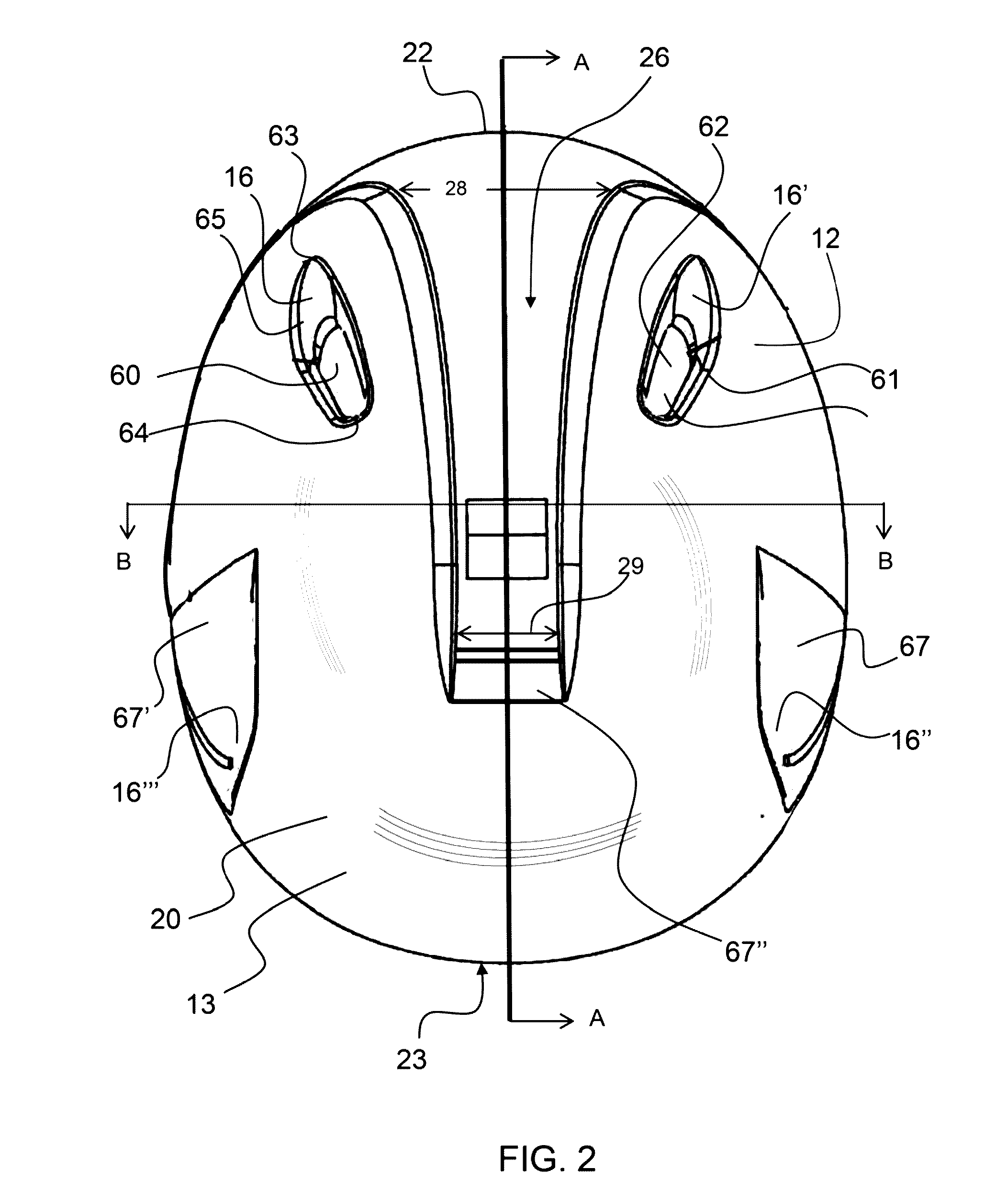
[0031]FIG. 2 shows a top down view of the exemplary helmet cover shown in FIG. 1, having a plurality of vents.

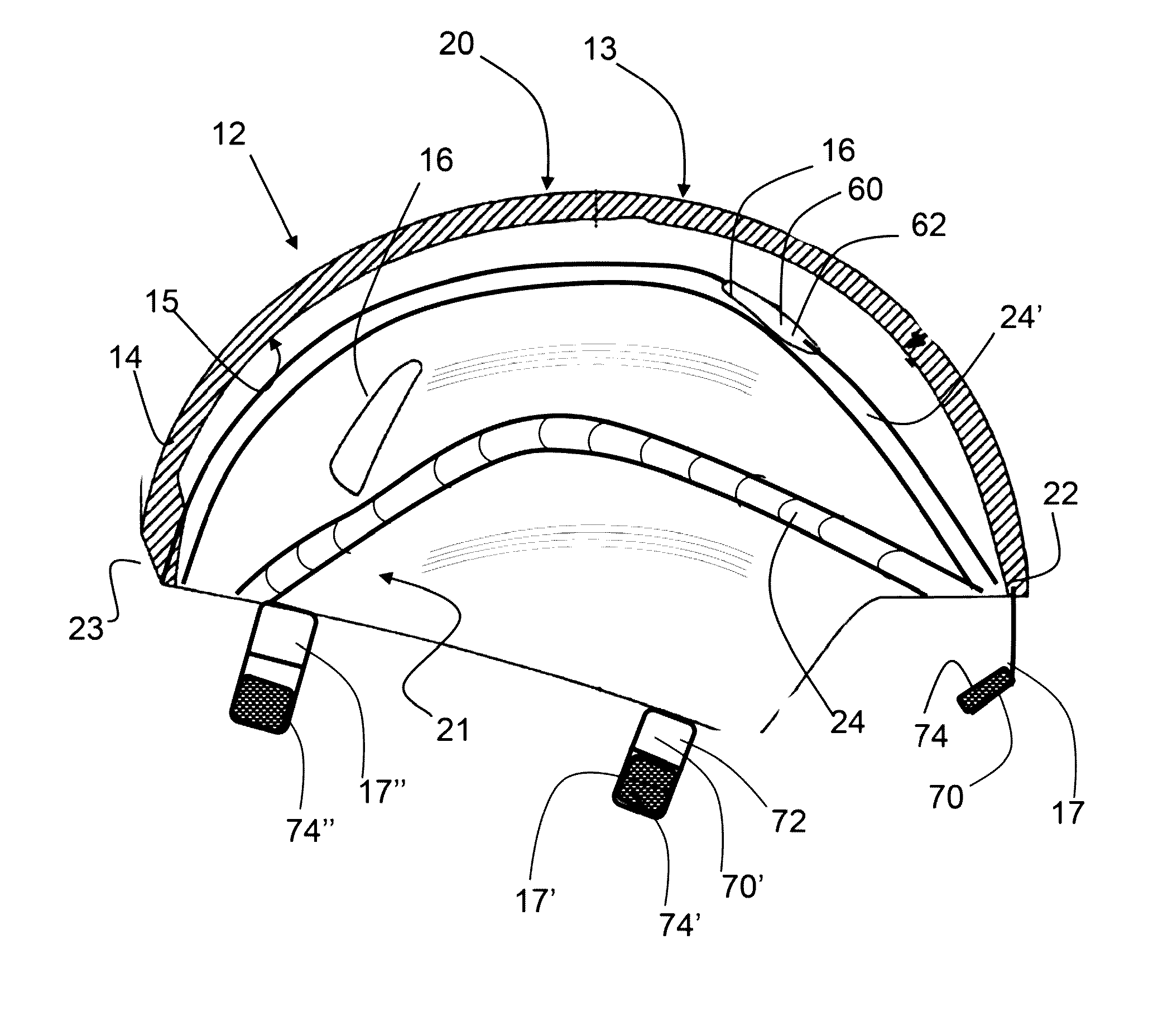
[0032]FIG. 3 shows a cut-away side view the inner surface of an exemplary helmet cover having attachment features and inner surface flow enhancer features.

[0033]FIG. 4 shows a cut-away view of an exemplary helmet cover having an attachment feature and an inner surface flow enhancer feature.

[0034]FIG. 5 shows an isometric view of an exemplary helmet cover having interchangeable pads.

[0035]FIG. 6 shows an isometric view of an exemplary helmet cover having a vent opening configured to at least partially align with a vent opening in a helmet.

[0036]FIG. 7 shows, a cut-away view of an exemplary helmet cover having an inner surface flow enhancer feature.

[0037]FIG. 8 shows a cut-away view of an exemplary helmet cover having ari inner surface flow enhancer feature that extends between two ven...


PUM


Abstract

A helmet cover that has an outer skin, an impact absorbing material and at least one vent comprising an aperture through the helmet cover is described. A helmet cover vent may be aligned with a vent in a helmet, thereby providing for improved ventilation and cooling, and may be attached to a helmet. A helmet cover vent may be configured as a tapered or flared vent, and may be an, air capture vent. The impact absorbing material may be configured over substantially the entire helmet cover surface, or may cover only a portion of the surface. In one embodiment, the impact absorbing material is configured as a discrete pad that is located where impact is most common, such as on the front, sides, or back of the helmet cover. A discrete pad may be interchangeable, allowing for customizing the type and location of impact absorption on the helmet cover.

Description

CROSS REFERENCE TO RELATED APPLICATIONS[0001]This application is a continuation in part of PCT patent application no. PCT / US2015 / 039824 filed on Jul. 9, 2015 and entitled HELMET COVER, and a continuation in part of U.S. patent application Ser. No. 14 / 328,899, filed on Jul. 10, 2014, entitled HELMET COVER, currently pending which is a continuation in part of U.S. patent application Ser. No. 13 / 791,813 filed on Mar. 8, 2013, entitled HELMET COVER and issued as U.S. Pat. No. 8,776,272 on Jul. 15, 2014, which claims the benefit of U.S. Provisional Application No. 61 / 608,450 filed on Mar. 8, 2012, entitled HELMET COVER; all of which are incorporated herein by reference in their entirety.BACKGROUND OF THE INVENTION[0002]1. Field of the Invention[0003]The present invention relates to helmets having improved impact deflection and absorption properties and particularly helmets comprising a helmet cover portion.[0004]2. Background[0005]Repetitive impact to the head can lead to very serious an...

Claims


Application Information

Patent Timeline
Patent Type & Authority Applications(United States)
IPC IPC(8): A42B3/06A42B3/12A42B3/28
CPCA42B3/063A42B3/121A42B3/127A42B3/283A42B3/003
Inventor LYTLE, FRANK
Owner PROTECTIVE SPORTS EQUIP INT
Why Eureka
Try Eureka