Shock absorber

a technology of shock absorber and shock absorber, which is applied in the field of shock absorbers, can solve the problems of difficult to suppress vibration at a frequency higher than several hz, and achieve the effect of improving riding comfort in the vehicle, not sacrificing the stroke length of the shock absorber, and not impaired mountability in the vehicl

Active Publication Date: 2016-10-06
KYB CORP
View PDF7 Cites 14 Cited by
  • Summary
  • Abstract
  • Description
  • Claims
  • Application Information

AI Technical Summary

Benefits of technology

[0004]In the above-described shock absorber, since the damping force can be adjusted, the shock absorber can exert a damping force that is optimally suited to the vibration of a vehicle body, thereby improving the riding comfort in the vehicle. Further, since the damping force variable valve is provided outside of the cylinder, the above-described shock absorber is advantageous because the stroke length of the shock absorber is not sacrificed and the mountability in a vehicle is not impaired compared to a shock absorber in which the damping force variable valve is provided to the piston.

Problems solved by technology

Therefore, the frequency upper limit of the vehicle body vibration that can be damped by the shock absorber by adjusting the damping force is currently restricted to several Hz by the responsiveness of the damping force variable valve and the calculation processing speed of the ECU, and thus it is difficult suppress vibration at a frequency higher than several Hz.

Method used


Image

  • Shock absorber
  • Shock absorber
  • Shock absorber

Examples


first embodiment

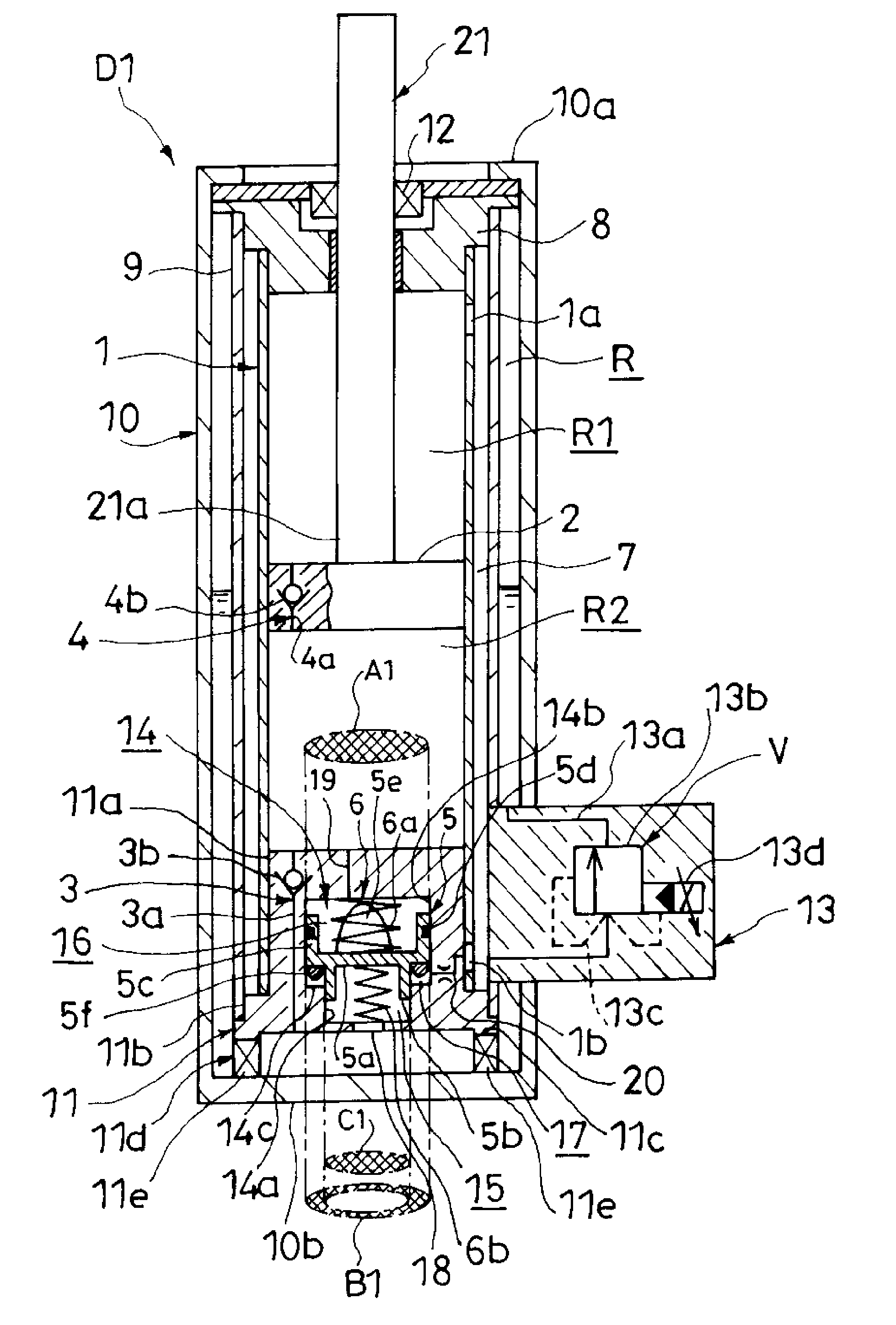
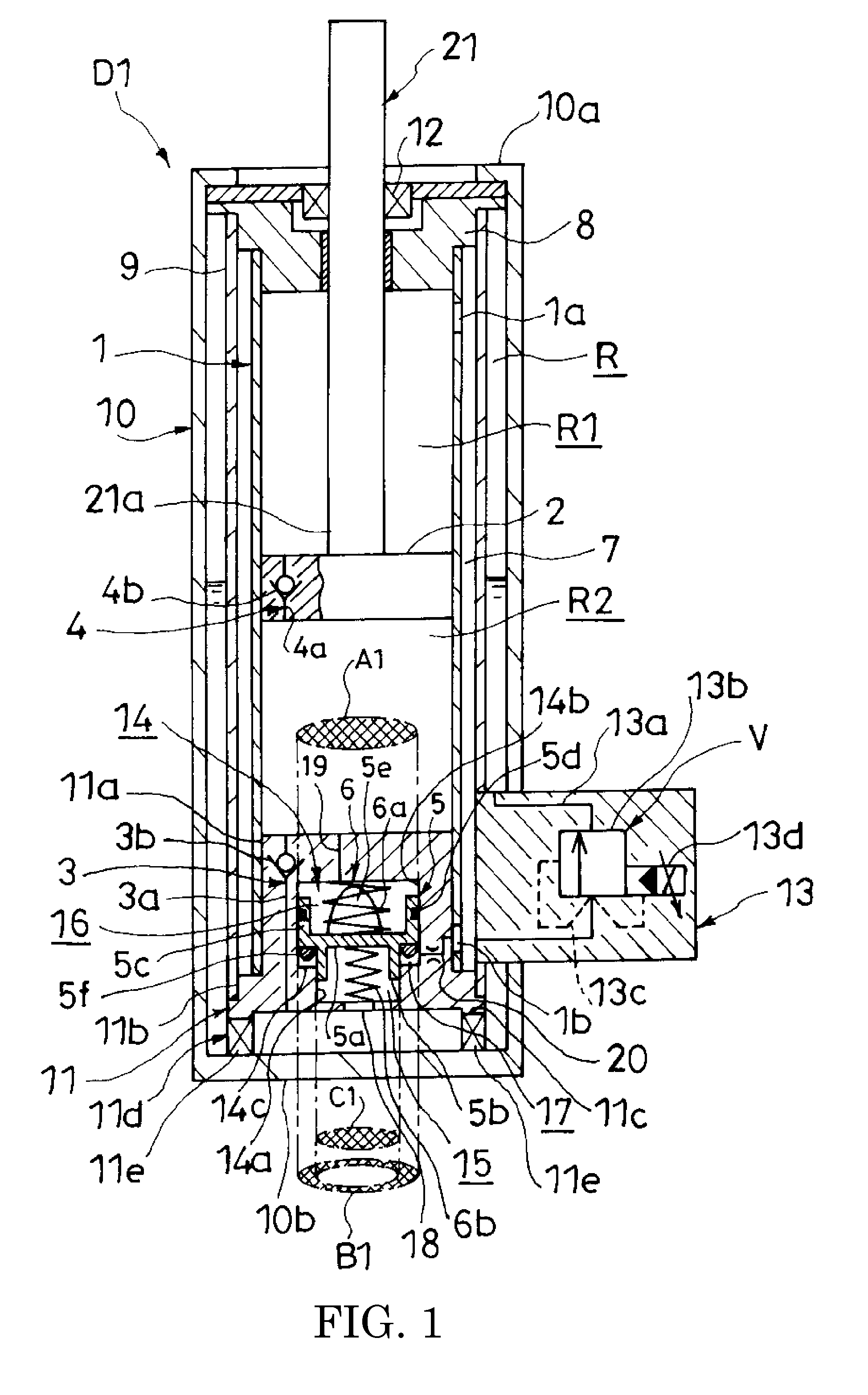
[0030]First, a shock absorber D1 according to a first embodiment of the present invention will be explained.

[0031]As shown in FIG. 1, the shock absorber D1 has a tubular cylinder 1, a piston 2 that is slidably inserted into the cylinder 1 and partitions the inside of the cylinder 1 into two chambers which are an extension-side chamber R1 and a compression-side chamber R2, a reservoir R, a suction passage 3 that permits only a flow of working oil from the reservoir R toward the compression-side chamber R2, a rectification passage 4 that permits only a flow of working oil from the compression-side chamber R2 toward the extension-side chamber R1, a damping force variable valve V serving as a damping force adjusting part that permits only a flow of working oil from the extension-side chamber R1 toward the reservoir R and can change a resistance applied to the flow of working oil, a bottom member 11 serving as a housing that has a pressure chamber 14 therein, a free piston 5 that is slid...

second embodiment

[0107]Next, a shock absorber D2 according to a second embodiment of the present invention will be explained in FIG. 5.

[0108]In the shock absorber D2, the reservoir R communicates with the outer periphery chamber 17, and the extension-side chamber R1 communicates with the small chamber 15 through an orifice passage 30. The shock absorber D2 differs from the shock absorber D1 in this point, but in all other points it is the same as the shock absorber D1. Hereinafter, constitutions that are the same as those in the shock absorber D1 will be assigned the same reference numerals in the drawings and detailed explanations thereof will be omitted.

[0109]The small chamber 15 communicates with the extension-side chamber R1 through the orifice passage 30, the through-hole 1b formed in the cylinder 1, and the discharge passage 7. The outer periphery chamber 17 communicates with the reservoir R through a passage 31 formed in the bottom member 11. The large chamber 16 communicates with the compres...

third embodiment

[0169]Next, a shock absorber D3 according to a third embodiment of the present invention will be explained. Hereinafter, constitutions that are the same as those in the first and second embodiments will be assigned the same reference numerals in the drawings and detailed explanations thereof will be omitted, and the following explanations will focus on the points of difference from the first and second embodiments.

[0170]The shock absorber D3 according to the third embodiment differs from the first and second embodiments in that it has a hydraulic cushion mechanism L that suppresses collisions between the bottom member 11 and the free piston 5 instead of a cushion member.

[0171]The shock absorber D3 will be explained below referring to FIG. 10. Hereinafter, the points of difference from the shock absorber D1 shown in FIG. 1 will be the focus of the explanation.

[0172]The hydraulic cushion mechanism L is a variable throttle valve, and is provided in the orifice passage 20 serving as an ...


PUM


Abstract

A shock absorber includes a suction passage permitting flow only from a reservoir toward a compression-side chamber, a rectification passage permitting flow only from the compression-side chamber toward an extension-side chamber, and a variable valve permitting flow only from the extension-side chamber toward the reservoir. A large chamber as a compression-side pressure chamber communicating with the compression-side chamber and an outer periphery chamber as an extension-side pressure chamber communicating with the extension-side chamber are partitioned in the shock absorber by a free piston that moves slidably within a bottom member serving as a housing. A compression-side pressure-receiving area of the free piston is larger than an extension-side pressure-receiving area. Therefore, even in the uniflow shock absorber with the extension-side chamber and the compression-side chamber at equal pressures during the contraction operation, the damping force is reduced under conditions in which high frequency is input since the free piston moves downward.

Description

TECHNICAL FIELD[0001]The present invention relates to a shock absorber.BACKGROUND ART[0002]A conventional shock absorber includes the following: a cylinder, a piston that is slidably inserted into the cylinder, a piston rod that is inserted into the cylinder and connected to a piston, an extension-side chamber and a compression-side chamber that are partitioned by the piston within the cylinder, an intermediate tube that covers an outer periphery of the cylinder and forms a discharge passage between itself and the cylinder, an outer tube that covers an outer periphery of the intermediate tube and forms a reservoir between itself and the intermediate tube, a suction passage that permits only a flow of working oil from the reservoir toward the compression-side chamber, a rectification passage that is provided to the piston and permits only a flow of working oil from the compression-side chamber toward the extension-side chamber, and a damping force variable valve provided between the ...

Claims


Application Information

Patent Timeline
Patent Type & Authority Applications(United States)
IPC IPC(8): B60G15/06F16F9/32F16F9/34F16F9/53B60G13/08F16F13/00
CPCB60G15/061B60G13/08F16F13/007F16F9/34B60G2600/182F16F9/3214B60G2202/12B60G2202/24B60G2204/424F16F9/53B60G17/08B60G2204/45B60G2600/44F16F9/187F16F9/5126F16F9/5165
Inventor TERAOKA, TAKASHIMASAMURA, TATSUYA
Owner KYB CORP
Why Eureka
Try Eureka