
Fusion method for cross traffic application using radars and camera

a cross-traffic application and camera technology, applied in automatic initiation, instruments, measurement devices, etc., can solve the problems of difficult to accurately correlate radar point data with camera image data, and it is not always possible to accurately estimate the heading of a remote vehicle or obj

Active Publication Date: 2016-10-06
GM GLOBAL TECH OPERATIONS LLC
View PDF25 Cites 58 Cited by
  • Summary
  • Abstract
  • Description
  • Claims
  • Application Information

AI Technical Summary

Benefits of technology

The present invention is a method and system for tracking objects that cross behind a vehicle. The system uses a vision system and two radar sensors to identify and track the target object. By combining the data from these sensors, the system can accurately estimate the velocity of the object, including its lateral component which is difficult to obtain using radar alone. This information is then used to trigger warnings or automatic braking in a Rear Cross Traffic Avoidance system to prevent accidents. The technical effects of this invention include improved accuracy in object detection and tracking, and better prevention of accidents in Rear Cross Traffic Avoidance systems.

Problems solved by technology

However, even with multiple object sensing inputs, such as radar and camera, it is not always possible to accurately estimate the heading of a remote vehicle or object, especially if the remote vehicle or object is moving in a predominantly lateral or tangential direction relative to the host vehicle.
Furthermore, in some situations, it is difficult to accurately correlate radar point data with camera image data.

Method used


Image

  • Fusion method for cross traffic application using radars and camera
  • Fusion method for cross traffic application using radars and camera
  • Fusion method for cross traffic application using radars and camera

Examples


Embodiment Construction

[0022]The following discussion of the embodiments of the invention directed to a method and apparatus for tracking objects in proximity to a host vehicle using a fusion of salient vision points and radar points is merely exemplary in nature, and is in no way intended to limit the invention or its applications or uses.

[0023]Many modern vehicles include an object sensing system for detecting objects in the path of the vehicle. The object sensing system can provide a warning to a driver, or even trigger other systems to take action to avoid a vehicle collision. Some vehicles also include an object sensing fusion system, which numerically “fuses” the data from two or more object detection sensors and then bases its object detection logic on the fused object data. One such fusion system is described in U.S. Pat. No. 7,460,951, titled “System and method of target tracking using sensor fusion”, which is assigned to the assignee of the present application, and which is hereby incorporated b...


PUM


Abstract

A method and system are disclosed for tracking objects which are crossing behind a host vehicle. Target data from a vision system and two radar sensors are provided to an object detection fusion system. Salient points on the target object are identified and tracked using the vision system data. The salient vision points are associated with corresponding radar points, where the radar points provide Doppler radial velocity data. A fusion calculation is performed on the salient vision points and the radar points, yielding an accurate estimate of the velocity of the target object, including its lateral component which is difficult to obtain using radar points only or traditional vision system methods. The position and velocity of the target object are used to trigger warnings or automatic braking in a Rear Cross Traffic Avoidance (RCTA) system.

Description

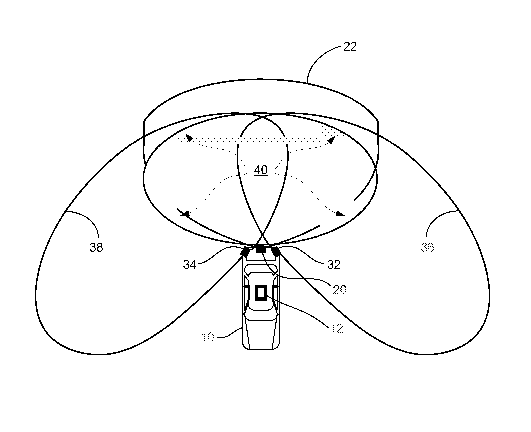
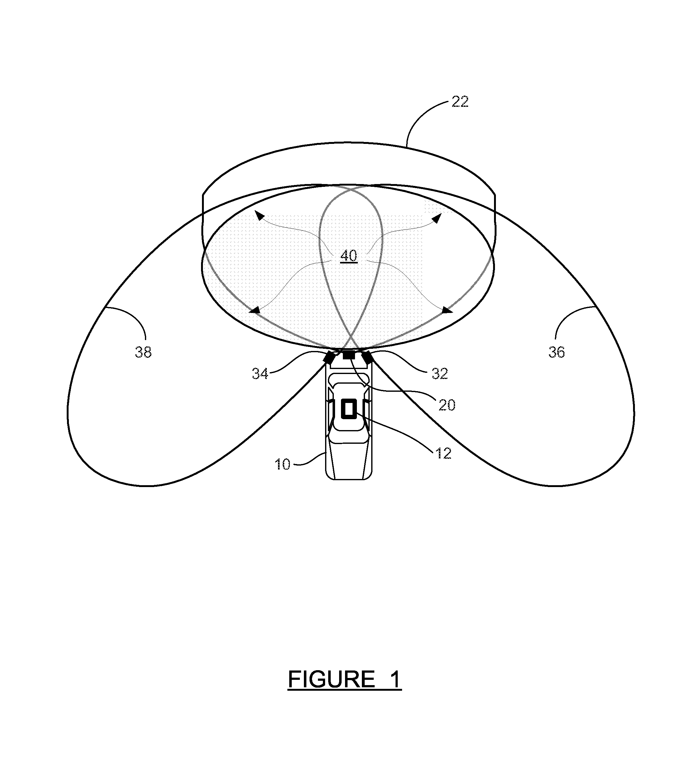
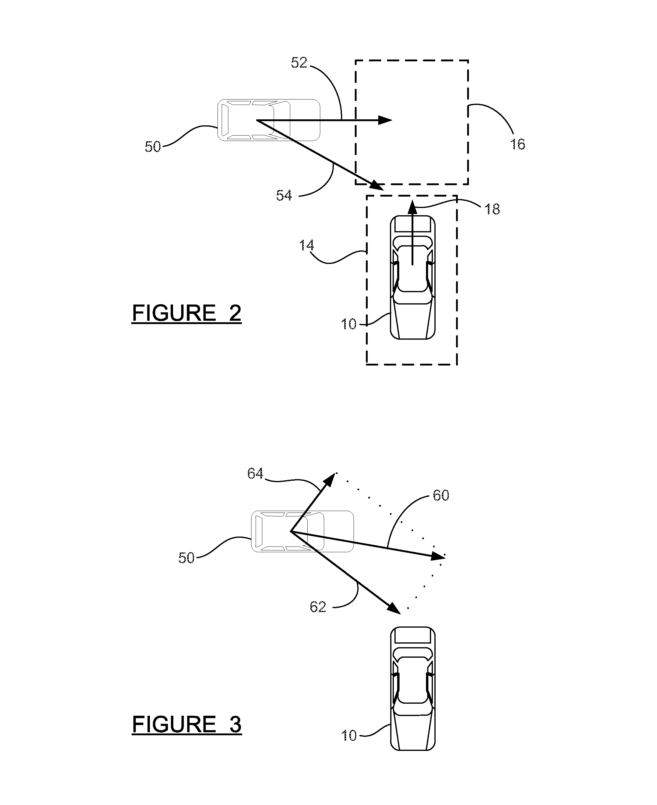
BACKGROUND OF THE INVENTION[0001]1. Field of the Invention[0002]This invention relates generally to a multiple-input object detection system and, more particularly, to a rear cross traffic avoidance system which combines camera-based and radar-based object data to track rear cross traffic objects, including a more accurate estimation of lateral velocity of the objects than would be possible with radar data alone.[0003]2. Discussion of the Related Art[0004]Object detection systems, also known as object sensing systems, have become increasingly common in modern vehicles. Object detection systems can provide a warning to a driver about an object in the path of a vehicle. Object detection systems can also provide input to active vehicle systems—such as Adaptive Cruise Control, which controls vehicle speed to maintain appropriate longitudinal spacing to a leading vehicle, and Rear Cross Traffic Avoidance systems, which can provide both warnings and automatic braking to avoid a collision ...

Claims


Application Information

Patent Timeline
IPC IPC(8): G01S13/93B60W30/08B60T7/22G01S13/86B60Q9/00G01S13/931
CPCG01S13/931G01S13/867B60W30/08B60T7/22B60Q9/008G01S13/589G01S2013/9317B60T2201/022B60T2210/32G01S13/874G01S2013/9315G01S2013/93274G01S2013/93272
Inventor ZENG, SHUQINGTONG, WEI
Owner GM GLOBAL TECH OPERATIONS LLC
Learn More