Check patentability & draft patents in minutes with Patsnap Eureka AI!

Holographic three-dimensional display system and method

Inactive Publication Date: 2016-10-06
AFC TECH
View PDF2 Cites 19 Cited by
  • Summary
  • Abstract
  • Description
  • Claims
  • Application Information

AI Technical Summary

Benefits of technology

The patent describes a holographic screen that uses a special micro structure to create a continuous output of different spatial frequencies. This allows for the display to show full-size three-dimensional objects without overlapping. The screen is placed between the information restoring lens array panel and the flat panel display. The zooming in or out of the display is also easy to achieve. The technical effect is a more immersive and seamless experience for viewers.

Problems solved by technology

Integrated photography (APPLIED OPTICS / Vol. 52, No. 4 / 1 February 2013) is theoretically an ideal three-dimensional light field collecting and display technology, but an inherent conflict between the imaging quality of a microlens array and the resolution of a displayed three-dimensional image is hard to overcome, namely, high resolution three-dimensional display requires the microlens array of a more fine size, but a microlens is too small and difficultly ensures subimage imaging quality of each lens, and a satisfactory true three-dimensional display effect is hard to obtain as so far.
But in an actual operation process, matching and control over the imaging quality of each single photography-projection device and the anchoring and calibrating of the array photography-projection apparatus cause difficulty to system integration; and meanwhile, massive use of a photography-projector will certainly increase a manufacturing cost of the system and is thus not likely to be accepted by common consumers.

Method used


Image

  • Holographic three-dimensional display system and method
  • Holographic three-dimensional display system and method
  • Holographic three-dimensional display system and method

Examples


application examples

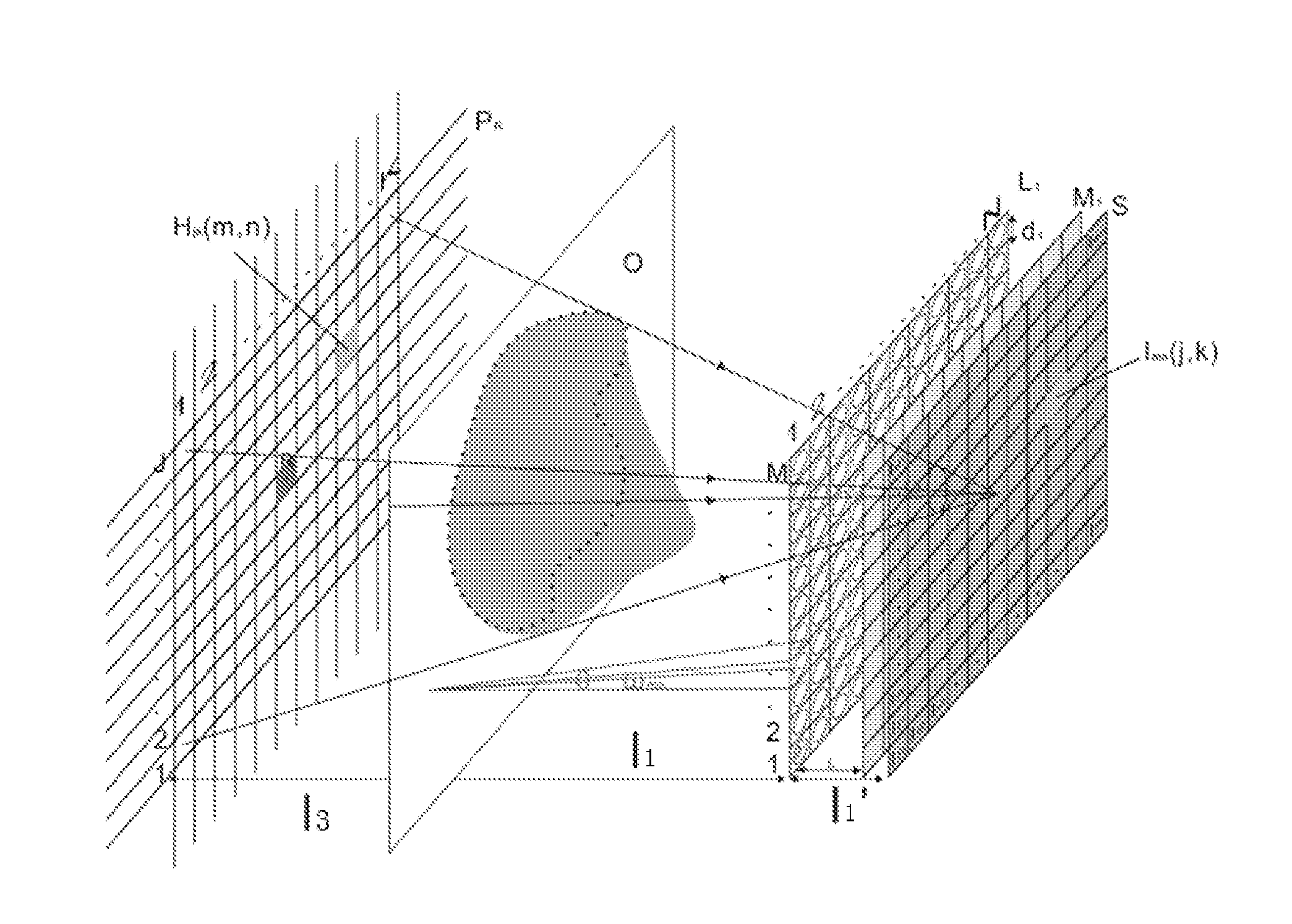
[0081]A current commercial 4K flat panel display is used to realize the total color total parallax digital holographic three-dimensional restoring displaying according to above principle, and specific display parameters are as follows: 1, a size of the hoxels Hjk′ is 4 mm*4 mm; 2, a number of the hoxels Hjk′ is J′*K′=211*118; 3, a number of spatial spectrums is M*N=36*36; and 4, an spatial observation angle is Ω=30°, and a display field of depth is about 50 cm.

[0082]FIG. 8 is a schematic diagram of an adopted lens array, and in order to make full use of the information capacity of finite plane pixels of the display, 3818 small lenses with a diameter of 10 mm are arrayed in a cellular arraying manner.

[0083]FIG. 9 is a holographic spatial spectrum coding schematic diagram in each small lens, an entity information collecting step is replaced with rendering of a computer virtual three-dimensional model, and a coding image is only limited to a head end cockpit part. FIG. 10 is pictures o...


PUM


Abstract

A holographic three-dimensional display system and a holographic three-dimensional display method are disclosed. Plane pixel information (J*K*M*N) of the flat panel display is reasonably used to convert the discrete spatial spectrum image information Imn into the discrete spatial spectrum image Sjk by using holographic coding conversion, the discrete spatial spectrum thereof is restored by using corresponding lens arrays, and the discrete spectrum widening of the sampling angle ωmn is realized by the holographic function screen so as to realize complete spatial spectrum restoring of an original three-dimensional space. By using the lens arrays and the holographic function screen, an inherent conflict between the imaging quality of a microlens array and the resolution of a displayed three-dimensional image in integration photography is effectively overcome, and eye visible perfect true three-dimensional display is realized, thereby obtaining eye visible prefect true three-dimensional display.

Description

[0001]PCT International Applications WO2010 / 072065, WO2010 / 072066 and WO2010 / 072067 are incorporated herein by reference in its entirety.BACKGROUND OF THE INVENTION[0002]1. Field of the Invention[0003]The present invention relates to a holographic three-dimensional display system and method.[0004]2. Related Arts[0005]Integrated photography (APPLIED OPTICS / Vol. 52, No. 4 / 1 February 2013) is theoretically an ideal three-dimensional light field collecting and display technology, but an inherent conflict between the imaging quality of a microlens array and the resolution of a displayed three-dimensional image is hard to overcome, namely, high resolution three-dimensional display requires the microlens array of a more fine size, but a microlens is too small and difficultly ensures subimage imaging quality of each lens, and a satisfactory true three-dimensional display effect is hard to obtain as so far. WO2010 / 072065, WO2010 / 072066 and WO2010 / 072067 disclose a real time color holographic...

Claims


Application Information

Patent Timeline
IPC IPC(8): G03H1/26G03H1/04G02B27/22G02B30/00G03B35/00
CPCG03H1/268G03H2223/19G03H1/0443G02B27/2214G03H1/04G03H1/22G03B35/00H04N13/232H04N13/363H04N13/307G02B30/00G02B30/27
Inventor FAN, CHENGCAI, ZHISENJIANG, CHAOCHUAN
Owner AFC TECH
Features
  • R&D
  • Intellectual Property
  • Life Sciences
  • Materials
  • Tech Scout
  • Unparalleled Data Quality
  • Higher Quality Content
  • 60% Fewer Hallucinations
Learn More