
Image processing apparatus and image processing method

a technology of image processing and image processing equipment, applied in the field of image processing equipment and image processing methods, can solve the problems of loss of information, large amount of information, and loss of information that is not intended by a content producer

Active Publication Date: 2016-10-06
SONY CORP
View PDF5 Cites 61 Cited by
  • Summary
  • Abstract
  • Description
  • Claims
  • Application Information

AI Technical Summary

Benefits of technology

The present technology provides an image processing apparatus and method that can convert the luminance of an image and perform dynamic range conversion based on the provided information. This technology can provide useful information related to luminance conversion and can improve the quality of images. Its effects can include improved image quality, improved dynamic range conversion, and improved information related to luminance conversion.

Problems solved by technology

However, in the display mapping, when conversion of a dynamic range is performed simply by linear scaling, it is concerned that a great amount of information is lost and a visual effect, which is seen by a human, of an image becomes greatly different before and after the conversion.
Such a loss of information is not intended by a content producer.

Method used


Image

  • Image processing apparatus and image processing method
  • Image processing apparatus and image processing method
  • Image processing apparatus and image processing method

Examples


Embodiment Construction

[0048]In the following, an embodiment of a technology disclosed in the present description will be described in detail with reference to the drawings.

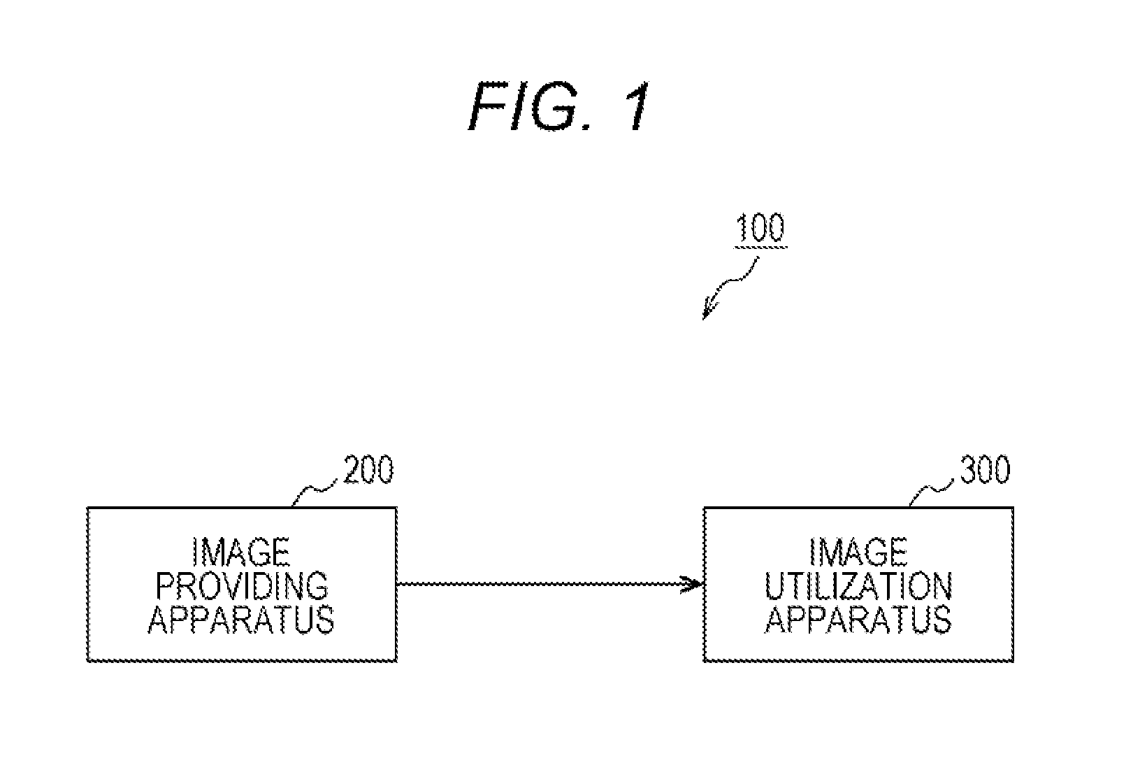
[0049]In FIG. 1, a configuration of an image providing system 100 to which a technology disclosed in the present description is applied is illustrated schematically. The illustrated image providing system 100 includes the image providing apparatus 200 to provide an image stream and an image utilization apparatus 300 to acquire an image stream and to perform display output of the image stream.

[0050]When the image providing system 100 is applied to a recording / reproduction system such as an ultra high definition-Blu-ray (registered trademark) disc (UHD-BD), the image providing apparatus 200 is on a side of a content producer. The image utilization apparatus 300 is a combination of a medium reproduction apparatus such as a BD player and a display to perform display output of a reproduced image. In the image providing system 100 such as an...


PUM


Abstract

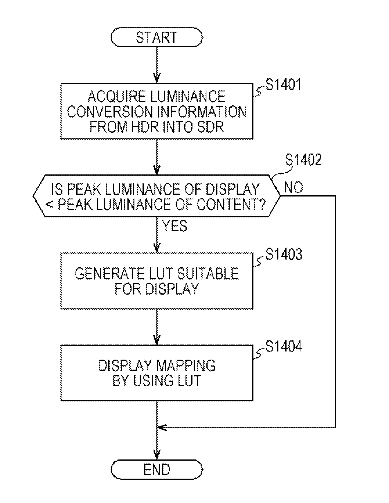
An image processing apparatus and an image processing method which can transmit / receive or display a high-dynamic-range image suitably are provided. An image transmission apparatus transfers, as metadata of content, luminance conversion information, which is for conversion of HDR content (for example, with maximum luminance 2000 nit) into SDR content (having, for example, 100 nit), or differential information. Based on the metadata, an image reception apparatus generates luminance conversion information, in which received HDR content is adapted to a capability of a display (for example, with maximum luminance 500 nit or 1000 nit) in an output destination, and realizes display mapping which is not against an intention of a producer.

Description

CROSS REFERENCE TO RELATED APPLICATIONS[0001]This application claims the benefit of Japanese Priority Patent Application JP 2014-182785 filed on Sep. 8, 2014, the entire contents of which are incorporated herein by reference.TECHNICAL FIELD[0002]A technology disclosed in the present description relates to an image processing apparatus and an image processing method which are for processing image information. Specifically, the technology relates to an image processing apparatus and an image processing method which are for transmitting / receiving or displaying a high-dynamic-range image.BACKGROUND ART[0003]Recently, the number of bits of an imaging element (image sensor) is increased and an image comes to be in a dynamic range. Generally, a dynamic range of an image can be expressed by a ratio between minimum luminance and peak luminance. In an HDR image, a contrast ratio between a color with a maximum color value and a color with a minimum color value is, for example, 10000:1 or highe...

Claims


Application Information

Patent Timeline
Patent Type & Authority Applications(United States)
IPC IPC(8): G06T5/00
CPCG06T5/009G06T2207/20008G06T2207/20208G06T2200/28H04N19/85H04N21/2343H04N21/2353H04N23/83G06T5/92H04N9/69
Inventor TSURU, TAKUMIETO, HIROAKIHAMADA, TOSHIYAKANAI, KENICHISHIRAISHI, TOMIZO
Owner SONY CORP
Learn More